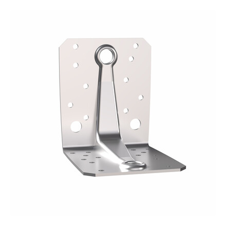
BOAX-II A4 throughbolt
Product Details
Features
Material
Inox A4
Benefits
• Efficient and economical installation.
• Simple drilling: Ø = thread diameter drilling.
• Variable anchors = various diameters and lengths
• Efficient and economical installation.
• Simple drilling: Ø = thread diameter drilling.
• Variable anchors = various diameters and lengths
Application
Header member
- Concrete and reinforced concrete
- solid materials
For Use With
• consolidation of wooden structures-shoes
• Fixing the steel and metal: railings, brackets, cable trays etc.
• Static and quasi-static anchors gates and machinery
Technical Data
Product Dimensions
References | Item Code | Seismic class C1/C2 | Tun / DB nr. | NOB nr. | Thread size [mm] [mm] | Total Length [L] [mm] | Max. Fixture Thickness [tfix] [mm] | Thread length [F] [mm] | Ø Fixture Hole [df] [mm] | Depth of the drilling hole [hef] [mm] | Ø x Depth of Drilled Hole [d0 x h1] [mm] | Packaging |
---|---|---|---|---|---|---|---|---|---|---|---|---|
BOAX-II M8-72/10 A4 | BOAXII08045010A4 | C1 | - | - | 8 | 72 | 10 | 32 | 9 | 45 | 8x60 | 50 |
BOAX-II M8-92/30 A4 | BOAXII08045030A4 | C1 | - | - | 8 | 92 | 30 | 52 | 9 | 45 | 8x60 | 50 |
BOAX-II M8-112/50 A4 | BOAXII08045050A4 | C1 | - | - | 8 | 112 | 50 | 72 | 9 | 45 | 8x60 | 40 |
BOAX-II M10-92/10 A4 | BOAXII10060010A4 | C1 | - | - | 10 | 92 | 10 | 47 | 12 | 60 | 10x75 | 40 |
BOAX-II M10-102/20 A4 | BOAXII10060020A4 | C1 | - | - | 10 | 102 | 20 | 57 | 12 | 60 | 10x75 | 25 |
BOAX-II M10-112/30 A4 | BOAXII10060030A4 | C1 | - | - | 10 | 112 | 30 | 67 | 12 | 60 | 10x75 | 25 |
BOAX-II M10-132/50 A4 | BOAXII10060050A4 | C1 | - | - | 10 | 132 | 50 | 87 | 12 | 60 | 10x75 | 25 |
BOAX-II M12-103/5 A4 | BOAXII12070005A4 | C1 | - | - | 12 | 103 | 5 | 53 | 14 | 70 | 12x90 | 20 |
BOAX-II M12-118/20 A4 | BOAXII12070020A4 | C1 | - | - | 12 | 118 | 20 | 68 | 14 | 70 | 12x90 | 20 |
BOAX-II M12-128/30 A4 | BOAXII12070030A4 | C1 | - | - | 12 | 128 | 30 | 78 | 14 | 70 | 12x90 | 20 |
BOAX-II M12-148/50 A4 | BOAXII12070050A4 | C1 | - | - | 12 | 148 | 50 | 98 | 14 | 70 | 12x90 | 20 |
BOAX-II M12-163/65 A4 | BOAXII12070065A4 | C1 | - | - | 12 | 163 | 65 | 113 | 14 | 70 | 12x90 | 20 |
BOAX-II M16-123/5 A4 | BOAXII16085005A4 | C1 | - | - | 16 | 123 | 5 | 65 | 18 | 85 | 16x110 | 10 |
BOAX-II M16-138/20 A4 | BOAXII16085020A4 | C1 | - | - | 16 | 138 | 20 | 80 | 18 | 85 | 16x110 | 10 |
BOAX-II M16-168/50 A4 | BOAXII16085050A4 | C1 | - | - | 16 | 168 | 50 | 110 | 18 | 85 | 16x110 | 10 |
BOAX-II M20-170/20 A4* | BOAX2020110020A4 | - | - | - | 20 | 170 | 20 | 55 | 22 | 110 | 20x130 | 5 |
BOAX M20-220/70 A4* | BOAX2020110070A4 | - | - | - | 20 | 220 | 70 | 55 | 22 | 110 | 20x130 | 5 |
* Not part of the ETA
Seismic category C1: for fixing non-structural elements to structures
Operating Expenses - cracked concrete
References | cracked concrete | Bending moment [Mrds] [Nm] | |||||||||
---|---|---|---|---|---|---|---|---|---|---|---|
Tension - Nrec [Nrec] [kN] | Shear (1-3) [Vrec] [Vrec] [kN] | Tension [NRd] [kN] | Shear [VRd] [kN] | ||||||||
C20/25 | C30/37 | C40/50 | C50/60 | C20/25 | C30/37 | C40/50 | C50/60 | C20/25 | C20/25 | ||
BOAX-II M8-72/10 A4 | 2 | 2.2 | 2.4 | 2.5 | 5.2 | 6.3 | 6.3 | 6.3 | - | - | 10.5 |
BOAX-II M8-92/30 A4 | 2 | 2.2 | 2.4 | 2.5 | 5.2 | 6.3 | 6.3 | 6.3 | - | - | 10.5 |
BOAX-II M8-112/50 A4 | 2 | 2.2 | 2.4 | 2.5 | 5.2 | 6.3 | 6.3 | 6.3 | - | - | 10.5 |
BOAX-II M10-92/10 A4 | 3.6 | 3.9 | 4.3 | 4.6 | 9.7 | 9.7 | 9.7 | 9.7 | - | - | 21.4 |
BOAX-II M10-102/20 A4 | 3.6 | 3.9 | 4.3 | 4.6 | 9.7 | 9.7 | 9.7 | 9.7 | - | - | 21.4 |
BOAX-II M10-112/30 A4 | 3.6 | 3.9 | 4.3 | 4.6 | 9.7 | 9.7 | 9.7 | 9.7 | - | - | 21.4 |
BOAX-II M10-132/50 A4 | 3.6 | 3.9 | 4.3 | 4.6 | 9.7 | 9.7 | 9.7 | 9.7 | - | - | 21.4 |
BOAX-II M12-103/5 A4 | 4.8 | 5.2 | 5.7 | 6.1 | 14.3 | 14.3 | 14.3 | 14.3 | - | - | 37.6 |
BOAX-II M12-118/20 A4 | 4.8 | 5.2 | 5.7 | 6.1 | 14.3 | 14.3 | 14.3 | 14.3 | - | - | 37.6 |
BOAX-II M12-128/30 A4 | 4.8 | 5.2 | 5.7 | 6.1 | 14.3 | 14.3 | 14.3 | 14.3 | - | - | 37.6 |
BOAX-II M12-148/50 A4 | 4.8 | 5.2 | 5.7 | 6.1 | 14.3 | 14.3 | 14.3 | 14.3 | - | - | 37.6 |
BOAX-II M12-163/65 A4 | 4.8 | 5.2 | 5.7 | 6.1 | 14.3 | 14.3 | 14.3 | 14.3 | - | - | 37.6 |
BOAX-II M16-123/5 A4 | 9.5 | 10.5 | 11.4 | 12.2 | 26.9 | 26.9 | 26.9 | 26.9 | - | - | 95.2 |
BOAX-II M16-138/20 A4 | 9.5 | 10.5 | 11.4 | 12.2 | 26.9 | 26.9 | 26.9 | 26.9 | - | - | 95.2 |
BOAX-II M16-168/50 A4 | 9.5 | 10.5 | 11.4 | 12.2 | 26.9 | 26.9 | 26.9 | 26.9 | - | - | 95.2 |
BOAX-II M20-170/20 A4* | - | - | - | - | - | - | - | - | - | - | 185.4 |
BOAX M20-220/70 A4* | - | - | - | - | - | - | - | - | - | - | 185.4 |
* Not part of ETA
Recommended loads / for single anchors in uncracked concrete(4)
References | Non-cracked concrete | |||||||||
---|---|---|---|---|---|---|---|---|---|---|
Tension - Nrec(1-2) [Rds,N] [kN] | Shear - Vrec(1-3) [Rds,V] [kN] | Tension [NRd] [kN] | Shear [VRd] [kN] | |||||||
C20/25 | C30/37 | C40/50 | C50/60 | C20/25 | C30/37 | C40/50 | C50/60 | |||
BOAX-II M8-72/10 A4 | 3.6 | 3.9 | 4.3 | 4.6 | 6.3 | 6.3 | 6.3 | 6.3 | - | - |
BOAX-II M8-92/30 A4 | 3.6 | 3.9 | 4.3 | 4.6 | 6.3 | 6.3 | 6.3 | 6.3 | - | - |
BOAX-II M8-112/50 A4 | 3.6 | 3.9 | 4.3 | 4.6 | 6.3 | 6.3 | 6.3 | 6.3 | - | - |
BOAX-II M10-92/10 A4 | 6.3 | 7 | 7.6 | 8.1 | 9.7 | 9.7 | 9.7 | 9.7 | - | - |
BOAX-II M10-102/20 A4 | 6.3 | 7 | 7.6 | 8.1 | 9.7 | 9.7 | 9.7 | 9.7 | - | - |
BOAX-II M10-112/30 A4 | 6.3 | 7 | 7.6 | 8.1 | 9.7 | 9.7 | 9.7 | 9.7 | - | - |
BOAX-II M10-132/50 A4 | 6.3 | 7 | 7.6 | 8.1 | 9.7 | 9.7 | 9.7 | 9.7 | - | - |
BOAX-II M12-103/5 A4 | 7.9 | 8.7 | 9.5 | 10.2 | 14.3 | 14.3 | 14.3 | 14.3 | - | - |
BOAX-II M12-118/20 A4 | 7.9 | 8.7 | 9.5 | 10.2 | 14.3 | 14.3 | 14.3 | 14.3 | - | - |
BOAX-II M12-128/30 A4 | 7.9 | 8.7 | 9.5 | 10.2 | 14.3 | 14.3 | 14.3 | 14.3 | - | - |
BOAX-II M12-148/50 A4 | 7.9 | 8.7 | 9.5 | 10.2 | 14.3 | 14.3 | 14.3 | 14.3 | - | - |
BOAX-II M12-163/65 A4 | 7.9 | 8.7 | 9.5 | 10.2 | 14.3 | 14.3 | 14.3 | 14.3 | - | - |
BOAX-II M16-123/5 A4 | 16.7 | 18.3 | 20 | 21.3 | 26.9 | 26.9 | 26.9 | 26.9 | - | - |
BOAX-II M16-138/20 A4 | 16.7 | 18.3 | 20 | 21.3 | 26.9 | 26.9 | 26.9 | 26.9 | - | - |
BOAX-II M16-168/50 A4 | 16.7 | 18.3 | 20 | 21.3 | 26.9 | 26.9 | 26.9 | 26.9 | - | - |
BOAX-II M20-170/20 A4* | 13.9 | 13.9 | 13.9 | 13.9 | 13.9 | 13.9 | 13.9 | 13.9 | - | - |
BOAX M20-220/70 A4* | 13.9 | 13.9 | 13.9 | 13.9 | 13.9 | 13.9 | 13.9 | 13.9 | - | - |
* Not included in ETA-08/0276
1) The recommended loads have been calculated using the characteristic capacities stated in the ETA-assessment with the partial safety factors given in the ETAG001 and the partial safety factor for loads: f = 1.4.
2) The recommended axial loads are valid for unreinforced concrete and reinforced concrete with a rebar spacing s ≥ 15 cm (any diameter) or with a rebar spacing s ≥ 10 cm, if the rebar diameter is 10 mm or smaller.
3) The figures for shear are based on a single anchor without influence of concrete edges. For anchorages close to edges (c ≤ max [10 hef; 60d]) the concrete edge failure shall be checked per
ETAG 001, Annex C, design method A.
4) Concrete is considered non-cracked when the tensile stress within the concrete is \sigmaL + \sigmaR ≤ 0. In the absence of detailed verification \sigmaR = 3 N/mm² can be assumed ( \sigmaL equals the tensile
stress within the concrete induced by external loads, anchors loads included).
6) The recommended bending moment is only valid for threaded rods.
Design capacities - single anchor - no edge distances - Non-cracked concrete
References | Design capacity - Non-cracked concrete | ||||||||
---|---|---|---|---|---|---|---|---|---|
Tension - NRd [kN] | Shear - VRd [kN] | Bending moment - MRd [Nm] | |||||||
C20/25 | C30/37 | C40/50 | C50/60 | C20/25 | C30/37 | C40/50 | C50/60 | ||
BOAX-II M8-72/10 A4 | 5 | 5.5 | 6 | 6.4 | 8.8 | 8.8 | 8.8 | 8.8 | 17.6 |
BOAX-II M8-92/30 A4 | 5 | 5.5 | 6 | 6.4 | 8.8 | 8.8 | 8.8 | 8.8 | 17.6 |
BOAX-II M8-112/50 A4 | 5 | 5.5 | 6 | 6.4 | 8.8 | 8.8 | 8.8 | 8.8 | 17.6 |
BOAX-II M10-92/10 A4 | 8.9 | 9.8 | 10.7 | 11.4 | 13.6 | 13.6 | 13.6 | 13.6 | 36 |
BOAX-II M10-102/20 A4 | 8.9 | 9.8 | 10.7 | 11.4 | 13.6 | 13.6 | 13.6 | 13.6 | 36 |
BOAX-II M10-112/30 A4 | 8.9 | 9.8 | 10.7 | 11.4 | 13.6 | 13.6 | 13.6 | 13.6 | 36 |
BOAX-II M10-132/50 A4 | 8.9 | 9.8 | 10.7 | 11.4 | 13.6 | 13.6 | 13.6 | 13.6 | 36 |
BOAX-II M12-103/5 A4 | 11.1 | 12.2 | 13.3 | 14.2 | 20 | 20 | 20 | 20 | 63.2 |
BOAX-II M12-118/20 A4 | 11.1 | 12.2 | 13.3 | 14.2 | 20 | 20 | 20 | 20 | 63.2 |
BOAX-II M12-128/30 A4 | 11.1 | 12.2 | 13.3 | 14.2 | 20 | 20 | 20 | 20 | 63.2 |
BOAX-II M12-148/50 A4 | 11.1 | 12.2 | 13.3 | 14.2 | 20 | 20 | 20 | 20 | 63.2 |
BOAX-II M12-163/65 A4 | 11.1 | 12.2 | 13.3 | 14.2 | 20 | 20 | 20 | 20 | 63.2 |
BOAX-II M16-123/5 A4 | 23.3 | 25.7 | 28 | 29.9 | 37.6 | 37.6 | 37.6 | 37.6 | 160 |
BOAX-II M16-138/20 A4 | 23.3 | 25.7 | 28 | 29.9 | 37.6 | 37.6 | 37.6 | 37.6 | 160 |
BOAX-II M16-168/50 A4 | 23.3 | 25.7 | 28 | 29.9 | 37.6 | 37.6 | 37.6 | 37.6 | 160 |
BOAX-II M20-170/20 A4* | 19.5 | 19.5 | 19.5 | 19.5 | 19.5 | 19.5 | 19.5 | 19.5 | 259.6 |
BOAX M20-220/70 A4* | 19.5 | 19.5 | 19.5 | 19.5 | 19.5 | 19.5 | 19.5 | 19.5 | 259.6 |
1. The design loads loads have been calculated using the partial safety factors for resistances stated in ETA-approval(s). The loading figures are valid for unreinforced concrete and reinforced concrete with a rebar spacing s ≥ 15 cm (any diameter) or with a rebar spacing s ≥ 10 cm, if the rebar diameter is 10mm or smaller.
2. The figures for shear are based on a single anchor without influence of concrete edges. For anchorages close to edges (c ≤ max [10 hef; 60d]) the concrete edge failure shall be checked per ETAG 001, Annex C, design method A.
3. Concrete is considered non-cracked when the tensile stress within the concrete is\sigmaL +\sigmaR ≤ 0. In the absence of detailed verification\sigmaR = 3 N/mm² can be assumed (\sigmaL equals the tensile stress within the concrete induced by external loads, anchors loads included).
*Not covered by ETA-08/0276
Design capacities - single anchor - no edge distances - Cracked concrete
References | Design capacity - Non-cracked concrete | ||||||||
---|---|---|---|---|---|---|---|---|---|
Tension - NRd [kN] | Shear - VRd [kN] | Bending moment - MRd [Nm] | |||||||
C20/25 | C30/37 | C40/50 | C50/60 | C20/25 | C30/37 | C40/50 | C50/60 | ||
BOAX-II M8-72/10 A4 | 2.8 | 3.1 | 3.3 | 3.6 | 7.2 | 8.8 | 8.8 | 8.8 | 17.6 |
BOAX-II M8-92/30 A4 | 2.8 | 3.1 | 3.3 | 3.6 | 7.2 | 8.8 | 8.8 | 8.8 | 17.6 |
BOAX-II M8-112/50 A4 | 2.8 | 3.1 | 3.3 | 3.6 | 7.2 | 8.8 | 8.8 | 8.8 | 17.6 |
BOAX-II M10-92/10 A4 | 5 | 5.5 | 6 | 6.4 | 13.6 | 13.6 | 13.6 | 13.6 | 36 |
BOAX-II M10-102/20 A4 | 5 | 5.5 | 6 | 6.4 | 13.6 | 13.6 | 13.6 | 13.6 | 36 |
BOAX-II M10-112/30 A4 | 5 | 5.5 | 6 | 6.4 | 13.6 | 13.6 | 13.6 | 13.6 | 36 |
BOAX-II M10-132/50 A4 | 5 | 5.5 | 6 | 6.4 | 13.6 | 13.6 | 13.6 | 13.6 | 36 |
BOAX-II M12-103/5 A4 | 6.7 | 7.3 | 8 | 8.5 | 20 | 20 | 20 | 20 | 63.2 |
BOAX-II M12-118/20 A4 | 6.7 | 7.3 | 8 | 8.5 | 20 | 20 | 20 | 20 | 63.2 |
BOAX-II M12-128/30 A4 | 6.7 | 7.3 | 8 | 8.5 | 20 | 20 | 20 | 20 | 63.2 |
BOAX-II M12-148/50 A4 | 6.7 | 7.3 | 8 | 8.5 | 20 | 20 | 20 | 20 | 63.2 |
BOAX-II M12-163/65 A4 | 6.7 | 7.3 | 8 | 8.5 | 20 | 20 | 20 | 20 | 63.2 |
BOAX-II M16-123/5 A4 | 13.3 | 14.7 | 16 | 17.1 | 37.6 | 37.6 | 37.6 | 37.6 | 160 |
BOAX-II M16-138/20 A4 | 13.3 | 14.7 | 16 | 17.1 | 37.6 | 37.6 | 37.6 | 37.6 | 160 |
BOAX-II M16-168/50 A4 | 13.3 | 14.7 | 16 | 17.1 | 37.6 | 37.6 | 37.6 | 37.6 | 160 |
BOAX-II M20-170/20 A4* | - | - | - | - | - | - | - | - | - |
BOAX M20-220/70 A4* | - | - | - | - | - | - | - | - | - |
1. The design loads loads have been calculated using the partial safety factors for resistances stated in ETA-approval(s). The loading figures are valid for unreinforced concrete and reinforced concrete with a rebar spacing s ≥ 15 cm (any diameter) or with a rebar spacing s ≥ 10 cm, if the rebar diameter is 10mm or smaller.
2. The figures for shear are based on a single anchor without influence of concrete edges. For anchorages close to edges (c ≤ max [10 hef; 60d]) the concrete edge failure shall be checked per ETAG 001, Annex C, design method A.
3. Concrete is considered non-cracked when the tensile stress within the concrete is\sigmaL +\sigmaR ≤ 0. In the absence of detailed verification\sigmaR = 3 N/mm² can be assumed (\sigmaL equals the tensile stress within the concrete induced by external loads, anchors loads included).
*Not covered by ETA-08/0276
Recommended capacities - single anchor - no edge distances - Non-cracked concrete
References | Recommended capacity - Non-cracked concrete | ||||||||
---|---|---|---|---|---|---|---|---|---|
Tension - Nrec [kN] | Shear - Vrec [kN] | Bending moment - Mrec [Nm] | |||||||
C20/25 | C30/37 | C40/50 | C50/60 | C20/25 | C30/37 | C40/50 | C50/60 | ||
BOAX-II M8-72/10 A4 | 3.6 | 3.9 | 4.3 | 4.6 | 6.3 | 6.3 | 6.3 | 6.3 | 12.6 |
BOAX-II M8-92/30 A4 | 3.6 | 3.9 | 4.3 | 4.6 | 6.3 | 6.3 | 6.3 | 6.3 | 12.6 |
BOAX-II M8-112/50 A4 | 3.6 | 3.9 | 4.3 | 4.6 | 6.3 | 6.3 | 6.3 | 6.3 | 12.6 |
BOAX-II M10-92/10 A4 | 6.3 | 7 | 7.6 | 8.1 | 9.7 | 9.7 | 9.7 | 9.7 | 25.7 |
BOAX-II M10-102/20 A4 | 6.3 | 7 | 7.6 | 8.1 | 9.7 | 9.7 | 9.7 | 9.7 | 25.7 |
BOAX-II M10-112/30 A4 | 6.3 | 7 | 7.6 | 8.1 | 9.7 | 9.7 | 9.7 | 9.7 | 25.7 |
BOAX-II M10-132/50 A4 | 6.3 | 7 | 7.6 | 8.1 | 9.7 | 9.7 | 9.7 | 9.7 | 25.7 |
BOAX-II M12-103/5 A4 | 7.9 | 8.7 | 9.5 | 10.2 | 14.3 | 14.3 | 14.3 | 14.3 | 45.1 |
BOAX-II M12-118/20 A4 | 7.9 | 8.7 | 9.5 | 10.2 | 14.3 | 14.3 | 14.3 | 14.3 | 45.1 |
BOAX-II M12-128/30 A4 | 7.9 | 8.7 | 9.5 | 10.2 | 14.3 | 14.3 | 14.3 | 14.3 | 45.1 |
BOAX-II M12-148/50 A4 | 7.9 | 8.7 | 9.5 | 10.2 | 14.3 | 14.3 | 14.3 | 14.3 | 45.1 |
BOAX-II M12-163/65 A4 | 7.9 | 8.7 | 9.5 | 10.2 | 14.3 | 14.3 | 14.3 | 14.3 | 45.1 |
BOAX-II M16-123/5 A4 | 16.7 | 18.3 | 20 | 21.3 | 26.9 | 26.9 | 26.9 | 26.9 | 114.3 |
BOAX-II M16-138/20 A4 | 16.7 | 18.3 | 20 | 21.3 | 26.9 | 26.9 | 26.9 | 26.9 | 114.3 |
BOAX-II M16-168/50 A4 | 16.7 | 18.3 | 20 | 21.3 | 26.9 | 26.9 | 26.9 | 26.9 | 114.3 |
BOAX-II M20-170/20 A4* | 13.9 | 13.9 | 13.9 | 13.9 | 13.9 | 13.9 | 13.9 | 13.9 | 185.4 |
BOAX M20-220/70 A4* | 13.9 | 13.9 | 13.9 | 13.9 | 13.9 | 13.9 | 13.9 | 13.9 | 185.4 |
1. The recommended loads have been calculated using the partial safety factors for resistances stated in ETA-approval(s) and with a partial safety factor for actions of γF=1.4. The loading figures
are valid for unreinforced concrete and reinforced concrete with a rebar spacing s ≥ 15 cm (any diameter) or with a rebar spacing s ≥ 10 cm, if the rebar diameter is 10 mm or smaller.
2. The figures for shear are based on a single anchor without influence of concrete edges. For anchorages close to edges (c ≤ max [10 hef; 60d]) the concrete edge failure shall be checked per
ETAG 001, Annex C, design method A.
3. Concrete is considered non-cracked when the tensile stress within the concrete is\sigmaL +\sigmaR ≤ 0. In the absence of detailed verification\sigmaR = 3 N/mm² can be assumed (\sigmaL equals the tensile stress within the concrete induced by external loads, anchors loads included).
Recommended capacities - single anchor - no edge distances - Cracked concrete
References | Recommended capacity - Cracked concrete | ||||||||
---|---|---|---|---|---|---|---|---|---|
Tension - Nrec [kN] | Shear - Vrec [kN] | Bending moment - Mrec [Nm] | |||||||
C20/25 | C30/37 | C40/50 | C50/60 | C20/25 | C30/37 | C40/50 | C50/60 | ||
BOAX-II M8-72/10 A4 | 2 | 2.2 | 2.4 | 2.5 | 5.2 | 6.3 | 6.3 | 6.3 | 12.6 |
BOAX-II M8-92/30 A4 | 2 | 2.2 | 2.4 | 2.5 | 5.2 | 6.3 | 6.3 | 6.3 | 12.6 |
BOAX-II M8-112/50 A4 | 2 | 2.2 | 2.4 | 2.5 | 5.2 | 6.3 | 6.3 | 6.3 | 12.6 |
BOAX-II M10-92/10 A4 | 3.6 | 3.9 | 4.3 | 4.6 | 9.7 | 9.7 | 9.7 | 9.7 | 25.7 |
BOAX-II M10-102/20 A4 | 3.6 | 3.9 | 4.3 | 4.6 | 9.7 | 9.7 | 9.7 | 9.7 | 25.7 |
BOAX-II M10-112/30 A4 | 3.6 | 3.9 | 4.3 | 4.6 | 9.7 | 9.7 | 9.7 | 9.7 | 25.7 |
BOAX-II M10-132/50 A4 | 3.6 | 3.9 | 4.3 | 4.6 | 9.7 | 9.7 | 9.7 | 9.7 | 25.7 |
BOAX-II M12-103/5 A4 | 4.8 | 5.2 | 5.7 | 6.1 | 14.3 | 14.3 | 14.3 | 14.3 | 45.1 |
BOAX-II M12-118/20 A4 | 4.8 | 5.2 | 5.7 | 6.1 | 14.3 | 14.3 | 14.3 | 14.3 | 45.1 |
BOAX-II M12-128/30 A4 | 4.8 | 5.2 | 5.7 | 6.1 | 14.3 | 14.3 | 14.3 | 14.3 | 45.1 |
BOAX-II M12-148/50 A4 | 4.8 | 5.2 | 5.7 | 6.1 | 14.3 | 14.3 | 14.3 | 14.3 | 45.1 |
BOAX-II M12-163/65 A4 | 4.8 | 5.2 | 5.7 | 6.1 | 14.3 | 14.3 | 14.3 | 14.3 | 45.1 |
BOAX-II M16-123/5 A4 | 9.5 | 10.5 | 11.4 | 12.2 | 26.9 | 26.9 | 26.9 | 26.9 | 114.3 |
BOAX-II M16-138/20 A4 | 9.5 | 10.5 | 11.4 | 12.2 | 26.9 | 26.9 | 26.9 | 26.9 | 114.3 |
BOAX-II M16-168/50 A4 | 9.5 | 10.5 | 11.4 | 12.2 | 26.9 | 26.9 | 26.9 | 26.9 | 114.3 |
BOAX-II M20-170/20 A4* | - | - | - | - | - | - | - | - | - |
BOAX M20-220/70 A4* | - | - | - | - | - | - | - | - | - |
1. The recommended loads have been calculated using the partial safety factors for resistances stated in ETA-approval(s) and with a partial safety factor for actions of γF=1.4. The loading figures
are valid for unreinforced concrete and reinforced concrete with a rebar spacing s ≥ 15 cm (any diameter) or with a rebar spacing s ≥ 10 cm, if the rebar diameter is 10 mm or smaller.
2. The figures for shear are based on a single anchor without influence of concrete edges. For anchorages close to edges (c ≤ max [10 hef; 60d]) the concrete edge failure shall be checked per
ETAG 001, Annex C, design method A.
3. Concrete is considered non-cracked when the tensile stress within the concrete is\sigmaL +\sigmaR ≤ 0. In the absence of detailed verification\sigmaR = 3 N/mm² can be assumed (\sigmaL equals the tensile stress within the concrete induced by external loads, anchors loads included)
Installation
Installation
Installation
In these systems, the interior of the armature is pulled into the expansion sleeve and the sleeve is pressed against the borehole wall. This creates friction between the wellbore and the ever expanding anchor. This principle of action is reliable and allows a high load on the anchor.
Installation data
References | Ø drilling diameter [d0] [mm] | Depth of the drilling hole [h1] [mm] | Ø Fixture Hole [df] [mm] | Wrench Size [SW] | Installation Torque [Tinst] [Nm] | Effective Embedment Depth [hef] [mm] | Characteristic spacing - Scr,N [scr,N] [mm] | Minimum spacing [smin] [mm] | Characteristic edge distance - Ccr,N [ccr,N] [mm] | Minimum edge distance [cmin] [mm] | Min. Member Thickness [hmin] [mm] |
---|---|---|---|---|---|---|---|---|---|---|---|
BOAX-II M8-72/10 A4 | 8 | 60 | 9 | 13 | 20 | 45 | 135 | 50 | 68 | 50 | 100 |
BOAX-II M8-92/30 A4 | 8 | 60 | 9 | 13 | 20 | 45 | 135 | 50 | 68 | 50 | 100 |
BOAX-II M8-112/50 A4 | 8 | 60 | 9 | 13 | 20 | 45 | 135 | 50 | 68 | 50 | 100 |
BOAX-II M10-92/10 A4 | 10 | 75 | 12 | 17 | 35 | 60 | 180 | 55 | 90 | 50 | 120 |
BOAX-II M10-102/20 A4 | 10 | 75 | 12 | 17 | 35 | 60 | 180 | 55 | 90 | 50 | 120 |
BOAX-II M10-112/30 A4 | 10 | 75 | 12 | 17 | 35 | 60 | 180 | 55 | 90 | 50 | 120 |
BOAX-II M10-132/50 A4 | 10 | 75 | 12 | 17 | 35 | 60 | 180 | 55 | 90 | 50 | 120 |
BOAX-II M12-103/5 A4 | 12 | 90 | 14 | 19 | 70 | 70 | 210 | 60 | 105 | 55 | 140 |
BOAX-II M12-118/20 A4 | 12 | 90 | 14 | 19 | 70 | 70 | 210 | 60 | 105 | 55 | 140 |
BOAX-II M12-128/30 A4 | 12 | 90 | 14 | 19 | 70 | 70 | 210 | 60 | 105 | 55 | 140 |
BOAX-II M12-148/50 A4 | 12 | 90 | 14 | 19 | 70 | 70 | 210 | 60 | 105 | 55 | 140 |
BOAX-II M12-163/65 A4 | 12 | 90 | 14 | 19 | 70 | 70 | 210 | 60 | 105 | 55 | 140 |
BOAX-II M16-123/5 A4 | 16 | 110 | 18 | 24 | 120 | 85 | 255 | 70 | 128 | 85 | 170 |
BOAX-II M16-138/20 A4 | 16 | 110 | 18 | 24 | 120 | 85 | 255 | 70 | 128 | 85 | 170 |
BOAX-II M16-168/50 A4 | 16 | 110 | 18 | 24 | 120 | 85 | 255 | 70 | 128 | 85 | 170 |
BOAX-II M20-170/20 A4* | 20 | 130 | 22 | 30 | 240 | 110 | 400 | 400 | 300 | 300 | 180 |

BOAX M20-220/70 A4* | 20 | 130 | 22 | 30 | 240 | 110 | 400 | 400 | 300 | 300 | 180 |