C1 - C5
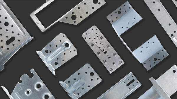
Bulldog-sided C1-C3-C5
Anchor blade, which is used to join two pieces of timber with pin.
CE Marking
Service class 3
Outdoor
Galvanised steel
Technical Data
Dimensions - Round double sided C1
| References | Type | Tun / DB nr. | NOB nr. | Connector dimensions [mm] | Box Quantity | ||||
|---|---|---|---|---|---|---|---|---|---|
| Diameter | Height | Thickness | |||||||
| External | Center hole | Teeth | Total | t | |||||
| dc | d1 | h1 | hc | ||||||
| C1-50 | C1 | 5804553 | 43910606 | 50 | 17 | 6 | 13 | 1 | 200 |
| C1-62-B | C1 | 5804554 | 43910614 | 62 | 21 | 7.4 | 16 | 1.2 | 100 |
| C1-75-B | C1 | 5804555 | NOB179 | 75 | 26 | 9.1 | 19.5 | 1.3 | 100 |
| C1-50G-B | C1 | 8271405 | 24793937 | 50 | 17 | 6 | 13 | 1 | 200 |
| C1-62G-B | C1 | 8271413 | 24793952 | 62 | 21 | 7.4 | 16 | 1.2 | 100 |
| C1-75G-B | C1 | 8271421 | 24793960 | 75 | 26 | 9.1 | 19.5 | 1.3 | 100 |
| C1-95G-B | C1 | 8271439 | 24793978 | 95 | 33 | 11.3 | 24 | 1.4 | 40 |
| C1-117G-B | C1 | 8977548 | 24793994 | 117 | 48 | 14.3 | 30 | 1.5 | 25 |
Minimum distances and characteristic values
| References | Type | Chosen timber thickness | Minimum distances | Characteristic shear resistance (bolt resistance not included) | ||||||
|---|---|---|---|---|---|---|---|---|---|---|
| t1 [mm] | t2 [mm] | Spacing parallel to grain | Spacing perpendicular to grain | from loaded end | from unloaded end | from loaded edge | from unloaded edge | Rv.k [kN] | ||
| a1 α=0° [mm] | a2 [mm] | a3.t [mm] | a3.c α=90° [mm] | a4.t α=90° [mm] | a4.c [mm] | |||||
| C1-50 | C1 | 18 | 30 | 75 | 60 | 75 | 75 | 40 | 30 | 6.3 |
| C1-62-B | C1 | 23 | 37 | 93 | 75 | 93 | 93 | 50 | 38 | 8.7 |
| C1-75-B | C1 | 28 | 46 | 113 | 90 | 113 | 113 | 60 | 45 | 11.6 |
| C1-50G-B | C1 | 18 | 30 | 75 | 60 | 75 | 75 | 40 | 30 | 6.3 |
| C1-62G-B | C1 | 23 | 37 | 93 | 75 | 93 | 93 | 50 | 38 | 8.7 |
| C1-75G-B | C1 | 28 | 46 | 113 | 90 | 113 | 113 | 60 | 45 | 11.6 |
| C1-95G-B | C1 | 34 | 57 | 143 | 114 | 143 | 143 | 76 | 57 | 16.6 |
| C1-117G-B | C1 | 43 | 72 | 176 | 141 | 176 | 176 | 94 | 71 | 22.7 |
| C3-73/130G-B | C3 | 40 | 67 | 146 | 117 | 146 | 146 | 78 | 59 | 17.1 |
| C5-100G-B | C5 | 22 | 37 | 150 | 120 | 150 | 150 | 80 | 60 | 18 |
| C5-130G-B | C5 | 28 | 47 | 195 | 156 | 195 | 195 | 104 | 78 | 26.6 |
The given characteristic shear resistance per connector Rv.k is calculated according to the minimum distances given in this table and for timber grade C24. This capacity can be increased with a higher timber grade (see k3 factor according to EN1995). This capacity can also be decreased with lower a3.t (see k2 factor according to EN1995). For lower t1 or t2, please refer to EN1995. The characteristic bolt shear resistance is not included and should be added.
Installation
Installation
Installation
- The installation is made while tightening the bolt, the teeth sink into the timber under the pressure of the bolt.
- The bolt installation always requires two washers.
Certification
Declaration of Performance (DoP)
uk-dop-h10-0007-04.pdf
(124.34 KB)


