Connector for Curtain Wall
This connector was developed to be used with timber curtain wall on concrete floor. It can be used in several configuration depending on the installation. Its special shape allows it to take important load without any deformation.
Technical Data
Dimensions and characteristic values
| References | Product capacities - Timber to Concrete | |||||||
|---|---|---|---|---|---|---|---|---|
| Number of Fasteners | Characteristic capacities - Timber C24 - Middle of concrete [kN] | |||||||
| Joist | Flange B | R1.k | R2.k = R3.k | R4.k | R5.k | |||
| Qty | Type | Qty | Type | CNA4.0x35 | CNA4.0x35 | CNA4.0x35 | CNA4.0x35 | |
| ACW155 | 13 | CNA4.0x35 | 2 | Ø12 | 16.3 | 15.3 | 21.1 | 5 |
Please note that the loads given in this table are maximum loads. If the anchors don't resist to these loads, they will be reduced.
These capacities are valid with anchors in holes close to the bend
The capacities are given for timber element that can't rotate.
Characteristic capacities - Timber to rigid support - Near concrete edge
| References | Product capacities - Timber to Concrete | ||||||||
|---|---|---|---|---|---|---|---|---|---|
| Number of Fasteners | Characteristic capacities - Timber C24 - Near concrete edge [kN] | ||||||||
| Joist | Flange B | R1.k | R2.k = R3.k | R4.k | R5.k | R6.k | |||
| Qty | Type | Qty | Type | CNA4.0x35 | CNA4.0x35 | CNA4.0x35 | CNA4.0x35 | CNA4.0x35 | |
| ACW155 | 13 | CNA4.0x35 | 2 | Ø12 | 8.8 | 8.9 | 6 | 11.4 | 21.2 |
Please note that the loads given in this table are maximum loads. If the anchors don't resist to these loads, they will be reduced.
These capacities are valid with anchors in holes far from the bend
Installation
Installation
Fasteners
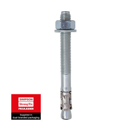
On concrete: 2 Throughbolt Ø12 or resin anchor + 2 threaded rod Ø12 (See bolt pattern)
Due to the high loads, the anchors resistance must be checked. The resistance of the ACW155 can be limited by the anchors.
On timber: 15 Nails CNA4.0x35 (see nail pattern) or bolt Ø10 or wood screw
Timber Element
All the timber elements attached to the angle bracket, must be designed by a skilled person. The timber element must be checked for splitting, deformation, load capcity and other possible failure.


