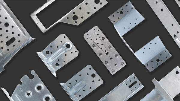
C10
Reversible gear GEKA C10
Along with the dowel serves to link two timber elements.
CE Marking
Service class 2
Technical Data
Product Dimensions
| References | Tun / DB nr. | NOB nr. | Dimensions and drill holes [mm] | |||
|---|---|---|---|---|---|---|
| dc | d1 | hc | t | |||
| C10-50 | TUN983 | 42295540 | 50 | 30.5 | 27 | 3 |
| C10-65 | TUN982 | 42295566 | 65 | 35.5 | 27 | 3 |
| C10-80 | TUN981 | 42295585 | 80 | 49.5 | 27 | 3 |
| C10-95 | TUN980 | 42295604 | 95 | 65.5 | 27 | 3 |
| C10-115 | TUN979 | 42295612 | 115 | 85.5 | 27 | 3 |
Capacities
| References | Characteristic Capacities [kN] |
|---|---|
| Rc,k | |
| C10-50 | 8.8 |
| C10-65 | 13.1 |
| C10-80 | 17.9 |
| C10-95 | 23.1 |
| C10-115 | 30.8 |
For the load capacity of the anchor plate, the values summed.
Must be a minimum distance drive dowels see EN1995-1-1
Dimensions - Geka double sided C10
| References | Type | Connector dimensions | ||||
|---|---|---|---|---|---|---|
| Diameter | Height | Thickness | ||||
| External | Center hole | Teeth | Total | t [mm] | ||
| dc [mm] | d1 [mm] | h1 [mm] | hc [mm] | |||
| C10-50 | C10 | 50 | 30.5 | 12 | 27 | 3 |
| C10-65 | C10 | 65 | 35.5 | 12 | 27 | 3 |
| C10-80 | C10 | 80 | 49.5 | 12 | 27 | 3 |
| C10-95 | C10 | 95 | 65.5 | 12 | 27 | 3 |
| C10-115 | C10 | 115 | 85.5 | 12 | 27 | 3 |
Minimum distances and characteristic values
| References | Type | Chosen timber thickness | Minimum distances | Characteristic shear resistance (bolt resistance not included) | ||||||
|---|---|---|---|---|---|---|---|---|---|---|
| t1 [mm] | t2 [mm] | Spacing parallel to grain | Spacing perpendicular to grain | from loaded end | from unloaded end | from loaded edge | from loaded edge | Rv.k [kN] | ||
| a1 α=0° [mm] | a2 [mm] | a3.t [mm] | a3.c α=90° [mm] | a4.t α=90° [mm] | a4.c [mm] | |||||
| C10-50 | C10 | 36 | 60 | 100 | 60 | 100 | 100 | 40 | 30 | 8.8 |
| C10-65 | C10 | 36 | 60 | 130 | 78 | 130 | 130 | 52 | 39 | 13.1 |
| C10-80 | C10 | 36 | 60 | 160 | 96 | 160 | 160 | 64 | 48 | 17.8 |
| C10-95 | C10 | 36 | 60 | 190 | 114 | 190 | 190 | 76 | 57 | 23.1 |
| C10-115 | C10 | 36 | 60 | 230 | 138 | 230 | 230 | 92 | 69 | 30.8 |
The given characteristic shear resistance per connector Rv.k is calculated according to the minimum distances given in this table and for timber grade C24. This capacity can be increased with a higher a3.t or a higher timber grade (see k2 and k3 factor according to EN1995). For lower t1 or t2, please refer to EN1995. The characteristic bolt shear resistance is not included and should be added.
Certification
Declaration of Performance (DoP)
uk-dop-h13-0020-02.pdf
(172.03 KB)
uk-dop-h13-0020-pdf.pdf
(36.25 KB)


