Angle bracket
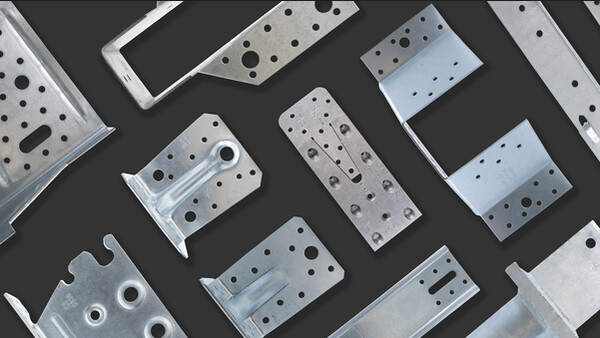
These brackets allow optimum connection between wood and other building materials such as concrete and steel. This is an economic connection that can be used in many areas. The types AKR and AKR-L differ in having either a hole or an oblong hole for the bolt, in the smaller flange.. AKR bracket is 3 mm thick and the edges are reinforced with rib.
Product Details
Features
Material
Steel:
S250GD + ZPRO
Corrosion protection:
ZPRO coating - corresponding to a zinc layer of approx. 55 μm
Benefits
- Load capacity in all directions
- Optimized capacities for partnailing and fullnailing
- One- or two-sided connections
- Possible mounting with distance from the support at tension connections
- Optimized bolt utilization
Application
Applications
Supporting member:
- Concrete, steel
Supported member:
- Solid wood, engineered wood
When to use
- The AKR brackets allow optimum connection between wood and other building materials such as concrete and steel.
According to their overall ZPRO surface the AKR-Z angle brackets could be used in outdoor areas
Technical Data
Product Dimensions
| References | Tun / DB nr. | NOB nr. | Product Dimensions [mm] | Holes flange A | Holes flange B | Box Quantity | |||||||
|---|---|---|---|---|---|---|---|---|---|---|---|---|---|
| A | B | C | t | Ø5 | Ø13.5 | Ø5 | Ø11 | Ø13.5 | Ø13.5x25 | ||||
| AKR95Z | 2048459 | 55360544 | 95 | 85 | 65 | 3 | 9 | - | 2 | 1 | 1 | - | 25 |
| AKR95LZ | 2048462 | 55360563 | 95 | 85 | 65 | 3 | 9 | - | 2 | 1 | - | 1 | 25 |
| AKR135Z | 2048465 | 55360578 | 135 | 85 | 65 | 3 | 14 | 1 | 2 | 1 | 1 | - | 25 |
| AKR135LZ | 2048466 | 55360616 | 135 | 85 | 65 | 3 | 14 | 1 | 2 | 1 | - | 1 | 25 |
| AKR285Z | 2048467 | 55360620 | 285 | 85 | 65 | 3 | 26 | 3 | 2 | 1 | 1 | - | 25 |
| AKR285LZ | 2048468 | 55360635 | 285 | 85 | 65 | 3 | 26 | 3 | 2 | 1 | - | 1 | 25 |
Below you will find load details to the nail pattern: fullnailing, partnailing and post connection. Further connection options, see the corresponding ETA.
Characterisitic capacities - Full nailing
| References | Product capacities - Timber to timber - Full nailing | |||||||||||
|---|---|---|---|---|---|---|---|---|---|---|---|---|
| Number of Fasteners | Nail pattern | Characteristic capacities - Timber C24 - 2 angle brackets per connection [kN] | ||||||||||
| Flange A | Flange B | R1.k | R2.k = R3.k | R4.k = R5.k | ||||||||
| Qty | Type | Qty | Type | CNA4.0x40 | CNA4.0x50 | CNA4.0x60 | CNA4.0x40 | CNA4.0x50 | CNA4.0x60 | CNA4.0x40/50/60 | ||
| AKR95Z | 8 | CNA* | 1 | M12** | 1 | min (17.55 ; 25.04/kmod + 13.2) | min (22.64 ; 25.04/kmod + 17.6) | min (26.48 ; 25.04/kmod + 22) | 5 | 6.2 | 6.9 | 15.75 / kmod |
| AKR95LZ | 8 | CNA* | 1 | M12** | 1 | min (13.31 ; 25.04/kmod + 8.92) | min (17.4 ; 25.04/kmod + 11.89) | min (20.89 ; 25.04/kmod + 14.87) | 4.4 | 5.6 | 6.4 | - |
| AKR135Z | 13 | CNA* | 1 | M12** | 5 | min (31.78 ; 25.04/kmod + 8.69) | min (40.69 ; 25.4/kmod + 11.58) | min (46.92 ; 25.04/kmod + 14.48) | 8 | 10.1 | 11.2 | 15.75 / kmod |
| AKR135LZ | 13 | CNA* | 1 | M12** | 5 | min (24.88 ; 25.04/kmod + 5.87) | min (32.34 ; 25.4/kmod + 7.83) | min (38.36 ; 25.04/kmod + 9.78) | 7.2 | 9.1 | 10.4 | - |
| AKR285Z | 25 | CNA* | 1 | M12** | 15 | min (45.25 ; 25.04/kmod + 8.69) | min (58.98 ; 25.04/kmod + 11.58) | min (70.31 ; 25.04/kmod + 14.48) | 8.9 | 11.6 | 14.1 | 15.75 / kmod |
| AKR285LZ | 25 | CNA* | 1 | M12** | 15 | min (32.96 ; 25.04/kmod + 5.87) | min (43.42 ; 25.04/kmod + 7.83) | min (52.87 ; 25.04/kmod + 9.78) | 6.6 | 8.7 | 10.7 | - |
* Refer to Characteristic Capacity table columns for type of fasteners that can be used in Flange A. Capacities vary depending on fastener type used.
** The bolt design resistance requirement R#,d is determined from (bolt factor x connection design load F#,d) for the required load direction and fastener. Refer to the Simpson Strong-Tie anchor product range for suitable anchors. Typical anchor solutions depend on the concrete type, spacing and edge distances.
| Factor for bolt calculation at 2 AKR connections | ||
| Load direction | kax | klat |
| F1 Bolt 1 and 2 | 0,5 | 0 |
| F2/3 Bolt 1 and 2 | 0,2 | 0,5 |
| F4/5 Bolt 1 from F1,d | 1 | 0 |
| F4/5 Bolt 2 | 0,5 | 1 |
For load direction F4/5 applies: An additional tensile load (F1,d) must be received and verified for the left AKR, and for both bolts.
Combined load:
Characteristic capacities - Partial nailing
| References | Product capacities - Timber to timber - Partial nailing | |||||||||||
|---|---|---|---|---|---|---|---|---|---|---|---|---|
| Number of Fasteners | Nail pattern | Characteristic capacities - Timber C24 - 2 angle brackets per connection [kN] | ||||||||||
| Flange A | Flange B | R1.k | R2.k = R3.k | R4.k = R5.k | ||||||||
| Qty | Type | Qty | Type | CNA4.0x40 | CNA4.0x50 | CNA4.0x60 | CNA4.0x40 | CNA4.0x50 | CNA4.0x60 | CNA4.0x40/50/60 | ||
| AKR95Z | 5 | CNA* | 1 | M12** | 3 | min (10.3 ; 25.04/kmod + 12.62) | min (13.34 ; 25.04/kmod + 16.82) | min (15.72 ; 25.04/kmod + 21.04) | 3.2 | 4 | 4.5 | 15.75 / kmod |
| AKR95LZ | 5 | CNA* | 1 | M12** | 3 | min (7.7 ; 25.04/kmod + 8.52) | min (10.1 ; 25.04/kmod + 11.36) | min (12.18 ; 25.04/kmod + 14.22) | 2.9 | 3.6 | 4.1 | - |
| AKR135Z | 9 | CNA* | 1 | M12** | 6 | min (21.19 ; 25.04/kmod + 8.69) | min (27.21 ; 25.04/kmod + 11.58) | min (31.54 ; 25.04/kmod + 11.58) | 5.9 | 7.5 | 8.4 | 15.75 / kmod |
| AKR135LZ | 9 | CNA* | 1 | M12** | 6 | min (16.39 ; 25.04/kmod + 5.87) | min (21.35 ; 25.04/kmod + 7.83) | min (25.45 ; 25.04/kmod + 9.78) | 5.2 | 6.6 | 7.6 | - |
| AKR285Z | 14 | CNA* | 1 | M12** | 17 | min (27.93 ; (25.04/kmod + 3.93) | min (36.23 ; 25.04/kmod + 5.24) | min (42.8 ; 25.04/kmod + 6.55) | 5.5 | 7.3 | 8.8 | 15.75 / kmod |
| AKR285LZ | 14 | CNA* | 1 | M12** | 17 | min (20.71 ; (25.04/kmod + 2.66) | min (27.2 ; 25.04/kmod + 3.54) | min (32.91 ; 25.04/kmod + 4.43) | 4.1 | 5.5 | 6.7 | - |
* Refer to Characteristic Capacity table columns for type of fasteners that can be used in Flange A. Capacities vary depending on fastener type used.
** The bolt design resistance requirement R#,d is determined from (bolt factor x connection design load F#,d) for the required load direction and fastener. Refer to the Simpson Strong-Tie anchor product range for suitable anchors. Typical anchor solutions depend on the concrete type, spacing and edge distances.
Characteristic capacities - Post connection
| References | Product capacities - Timber C24 - column | |||||||||||
|---|---|---|---|---|---|---|---|---|---|---|---|---|
| Number of Fasteners | Nail pattern | Characteristic capacities - Timber C24 - 2 angle brackets per connection [kN] | ||||||||||
| Flange A | Flange B | R1.k | R2.k = R3.k | R4.k = R5.k | ||||||||
| Qty | Type | Qty | Type | CNA4.0x40 | CNA4.0x50 | CNA4.0x60 | CNA4.0x40 | CNA4.0x50 | CNA4.0x60 | CNA4.0x40/50/60 | ||
| AKR95Z | 5 | CNA* | 1 | M12** | 2 | min (11.5 ; 25.04/kmod + 5.97) | min (14.78 ; 25.04/kmod + 7.97) | min (17.19 ; 25.04/kmod + 9.96) | 3.5 | 4.4 | 5 | 15.75 / kmod |
| AKR95LZ | 5 | CNA* | 1 | M12** | 2 | min (8.83 ; 25.04/kmod + 4.04) | min (11.52 ; 25.04/kmod + 5.38) | min (13.76 ; 25.04/kmod + 6.73) | 3.1 | 3.9 | 4.5 | - |
| AKR135Z | 8 | CNA* | 1 | M12** | 7 | min (20.49 ; 25.04/kmod + 3.93) | min (26.13 ; 25.04/kmod + 5.24) | min (29.94 ; 25.04/kmod + 6.55) | 5.6 | 7 | 7.9 | 15.75 / kmod |
| AKR135LZ | 8 | CNA* | 1 | M12** | 7 | min (16.31 ; 25.04/kmod + 2.66) | min (21.13 ; 25.04/kmod + 3.54) | min (24.91 ; 25.04/kmod + 4.43) | 4.9 | 6.2 | 7.1 | - |
| AKR285Z | 22 | CNA* | 1 | M12** | 16 | min (41.66 ; 25.04/kmod + 3.93) | min (54.19 ; 25.04/kmod + 5.24) | min (64.34 ; 25.04/kmod + 6.55) | 5.8 | 7.6 | 9.3 | 15.75 / kmod |
| AKR285LZ | 22 | CNA* | 1 | M12** | 16 | min (30.58 ; 25.04/kmod + 2.66) | min (40.23 ; 25.04/kmod + 3.54) | min (48.85 ; 25.04/kmod + 4.43) | 4.2 | 5.6 | 6.9 | - |
* Refer to Characteristic Capacity table columns for type of fasteners that can be used in Flange A. Capacities vary depending on fastener type used.
** The bolt design resistance requirement R#,d is determined from (bolt factor x connection design load F#,d) for the required load direction and fastener. Refer to the Simpson Strong-Tie anchor product range for suitable anchors. Typical anchor solutions depend on the concrete type, spacing and edge distances.
Installation
Installation
Fasteners
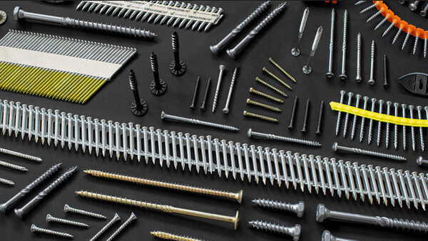
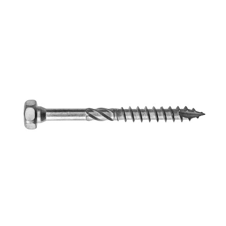
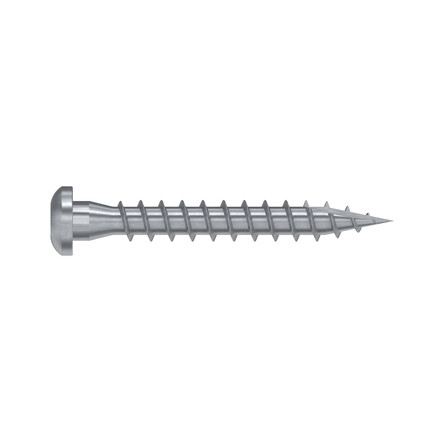
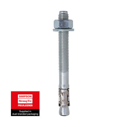
- The fixing needs to be done with CNA4,0xl threaded nails or CSA5,0xl screws. On concrete or steel by an wedge anchor M12 and a washer Ø24.
- It is possible to single or double sided connections.
