Large Reinforced Angle Bracket
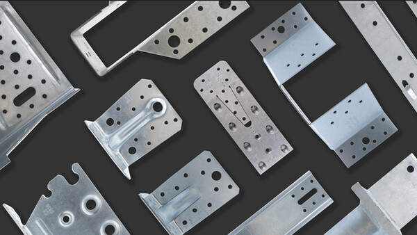
Reinforced angle brackets are suitable for structural applications in framing and wood-frame houses.
Product Details
Features
Material
- Galvanized steel S250GD + Z275 according to NF EN 10346.
Advantages
- High lateral capacity
- High rigidity
- Allow concrete header
Application
Header member
- Supporting member: solid wood, glued-laminated wood, concrete, steel, etc.
- Supported member: solid wood, composite lumber, glued-laminated wood, triangular trusses, profiles, etc.
Intended Use
- Fastening of small trusses.
- Cladding plates, cladding uprights.
- Rafter anchors, cantilevers, headers, etc.
Technical Data
Product Dimensions
| References | Product Dimensions [mm] | Joist | Holes flange B | Box Quantity | |||||
|---|---|---|---|---|---|---|---|---|---|
| A | B | C | t | Ø5 | Ø13 | Ø5 | Ø13 | ||
| AG922 | 121 | 79 | 150 | 2.5 | 26 | 2 | 18 | 2 | 25 |
Wood/wood connection beam/beam type - assembly with 2 angle brackets
| References | Product capacities - Timber beam to timber beam | |||
|---|---|---|---|---|
| Number of Fasteners | Characteristic capacities - Timber C24 - 2 angle brackets per connection [kN] | |||
| Joist | Flange B | R1.k | R2.k = R3.k | |
| Qty | Qty | CNA4.0x50 | CNA4.0x50 | |
| AG922 | 16 | 13 | 18.5 | 29.5 |
To obtain the resistance values for a single bracket, the values in the above table should be divided by two, provided that the supported beam is locked in rotation. Please consult our ETA-06/0106 if the beam is free to rotate.
Wood/wood connection post/beam type - assembly with 2 angle brackets
| References | Product capacities - Timber post to timber beam | ||
|---|---|---|---|
| Number of Fasteners | Characteristic capacities - Timber C24 - 2 angle brackets per connection [kN] | ||
| Joist | Flange B | R1.k | |
| Qty | Qty | CNA4.0x50 | |
| AG922 | 12 | 13 | 19.5 |
To obtain the resistance values for a single bracket, the values in the above table should be divided by two, provided that the supported beam is locked in rotation. Please consult our ETA-06/0106 if the beam is free to rotate.
Wood/rigid substrate connection beam/rigid substrate type - assembly with 2 angle brackets
| References | Product capacities - Timber beam to rigid support | |||||
|---|---|---|---|---|---|---|
| Number of Fasteners | Characteristic capacities - Timber C24 - 2 angle brackets per connection [kN] | |||||
| Joist | Flange B | R1.k | R2.k = R3.k | |||
| Qty | Type | Qty | Type | CNA4.0x50 | CNA4.0x50 | |
| AG922 | 16 | CNA* | 2 | Ø12 | 30.6 | 48.2 |
* Refer to Characteristic Capacity table columns for type of fasteners that can be used in Flange A. Capacities vary depending on fastener type used.
The bolt design resistance requirement R#,d is determined from (bolt factor x connection design load F#,d) for the required load direction and fastener. Refer to the Simpson Strong-Tie anchor product range for suitable anchors. Typical anchor solutions depend on the concrete type, spacing and edge distances.
To obtain the resistance values for a single bracket, the values in the above table should be divided by two, provided that the supported beam is locked in rotation. Please consult our ETA-06/0106 if the beam is free to rotate.
Wood/rigid substrate connection post/rigid substrate type - assembly with 2 angle brackets
| References | Product capacities - Timber post to rigid support | ||||
|---|---|---|---|---|---|
| Number of Fasteners | Characteristic capacities - Timber C24 - 2 angle brackets per connection [kN] | ||||
| Joist | Flange B | R1.k | |||
| Qty | Type | Qty | Type | CNA4.0x50 | |
| AG922 | 12 | CNA* | 2 | Ø12 | 37.5 |
* Refer to Characteristic Capacity table columns for type of fasteners that can be used in Flange A. Capacities vary depending on fastener type used.
The bolt design resistance requirement R#,d is determined from (bolt factor x connection design load F#,d) for the required load direction and fastener. Refer to the Simpson Strong-Tie anchor product range for suitable anchors. Typical anchor solutions depend on the concrete type, spacing and edge distances.
To obtain the resistance values for a single bracket, the values in the above table should be divided by two, provided that the supported beam is locked in rotation. Please consult our ETA-06/0106 if the beam is free to rotate.
Characteristic capacities - Beam/rigid support - Connection with 1 bracket - F4
| References | Characteristic capacities - Timber to rigid support | ||||
|---|---|---|---|---|---|
| Number of Fasteners | Characteristic capacities - Timber C24 - 1 angle brackets per connection [kN] | ||||
| Joist | Flange B | R4.k | |||
| Qty | Type | Qty | Type | CNA4.0x50 | |
| AG922 | 12 | CNA* | 2 | Ø12 | 24.8 |
Characteristic capacities - CLT beam to CLT beam - Ø12 connector screws - 2 angle brackets
| References | Product capacities - CLT beam to CLT beam - Ø12 connector screws - 2 angles brackets | |||||
|---|---|---|---|---|---|---|
| Fasteners | Characteristic capacities - Timber C24 - 2 angle brackets per connection [kN] | |||||
| Flange A | Flange B | R1.k | R2.k = R3.k | |||
| Qty | Type | Qty | Type | SSH12x80 | SSH12x80 | |
| AG922 | 2 | SSH | 2 | SSH | 23 | 23 |
Installation
Installation
Fasteners
On wood:
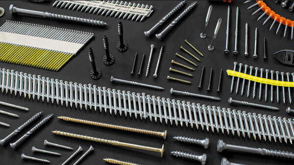
- CNA annular ring-shank nails dia. 4.0 x 35 or dia. 4.0 x 50 mm.
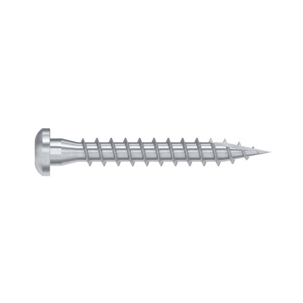
- CSA screws dia. 5.0 x 35 mm or CSA screws dia. 5.0 x 40 mm.
- Bolts.
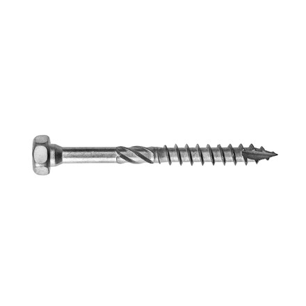
- LAG screws.
On concrete:
Concrete substrate
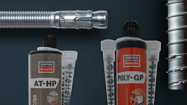
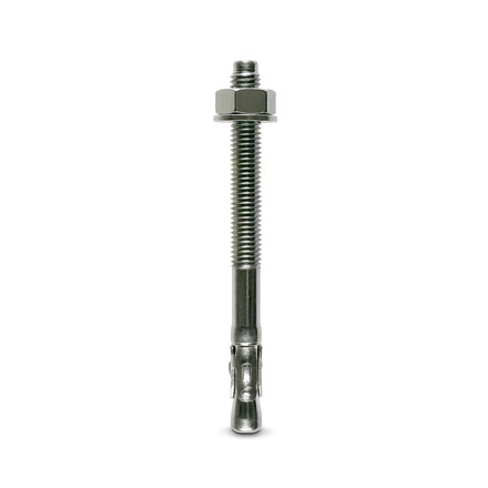
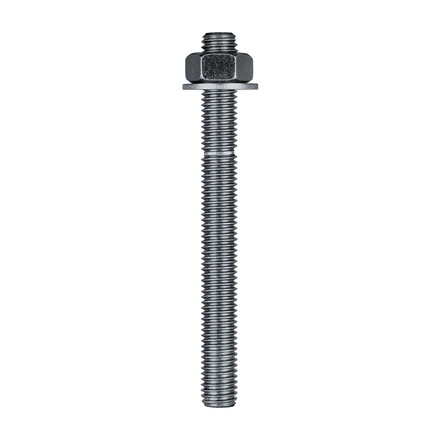
- Mechanical anchor: WA M10-78/5 OR WA M12-104/5 pin.
- Chemical anchor: AT-HP resin + LMAS M10-120/25 or LMAS M12-150/35 threaded rod.
Hollow masonry substrate:
- Chemical anchor: AT-HP or POLY-GP resin + LMAS M12-150/35 threaded rod + SH M16-130 screen.
On steel:
- Bolts.
Installation
- Come with the joist close to the header,
- Add nails/screws to fix the angle bracket to the joist,
- If timber header, the angle bracket is also fixed to the header with screws or nails
- If concrete header, attached the angle bracket using installation details from the anchor
Technical Notes
Technical information
F1: tensile force in the central axis of the angle-bracket
Particular situation of a fastening with only one angle-bracket:
- If the overall structure prevents the rotation of the purlin or the post, the tensile strength is equal to half of the given value for two angle-brackets.
- Otherwise, the connection resistance depends on the « f » distance between the vertical contact surface and the point of load application.
F2 and F3: shear lateral force
Particular situation of a connection with only one angle-bracket:
- The resistance value to consider is equal to half of the one given for two angle-brackets.
F4 and F5: transversal force directed towards or opposite the angle-bracket
- The connection resistance depends on the « e » distance between the base of the angle-bracket and the point of load application.
- To consult corresponding loads, contact us.
Only F1, F2 and F3 forces for connections with 2 angle-brackets are present on this sheet.
For more information, contact us.
