Joist hangers external flange
SBE is a joist hanger that provides a load bearing capacity similar to the model with 2 mm thickness. It is the first joist hanger resulting from a study carried out according to Eurocode 5 specifications.
Product Details
Features
Material
- Galvanized steel S250GD + Z275 according to NF EN 10346.
- Thickness 1.5 mm.
Advantages
- Joist hanger optimized for faster installation (20% less nailing compared to SAE).
- Speed prong for easier installation on wood substrate.
- Lower thickness without loss of resistance.
Application
Support
- Supporting member: solid wood, composite lumber, glued-laminated wood, concrete, steel.
- Supported member: solid wood, composite lumber, glued-laminated wood.
Intend Use
- Joists, purlins.
- Smooth beams and cladding uprights.
- Rafter ends.
- Refurbishment of existing assemblies, etc.
Technical Data
Product Dimensions
| References | Tun / DB nr. | NOB nr. | Joist Size [mm] | Product Dimensions [mm] | Header holes | Joist holes | ||||||||
|---|---|---|---|---|---|---|---|---|---|---|---|---|---|---|
| Width | Height | A | B | C | D | F | t | Ø5 | Ø11 | Ø5 | ||||
| Min | Max. | |||||||||||||
| SBE40/110 | 5086538 | 26224352 | 40 | 123 | 165 | 40 | 110 | 55 | 30 | 54 | 1.5 | 12 | 2 | 8 |
| SBE40/140 | 5086549 | 28736114 | 40 | 153 | 210 | 40 | 140 | 55 | 30 | 54 | 1.5 | 14 | 2 | 10 |
| SBE45/93 | 5086529 | 25911793 | 45 | 105 | 139 | 45 | 92.5 | 55 | 30 | 54 | 1.5 | 12 | 2 | 6 |
| SBE45/108 | 5086539 | 26224360 | 45 | 120 | 162 | 45 | 107.5 | 55 | 30 | 54 | 1.5 | 12 | 2 | 8 |
| SBE45/138 | 5086550 | 28755585 | 45 | 150 | 207 | 45 | 137.5 | 55 | 30 | 54 | 1.5 | 14 | 2 | 10 |
| SBE45/168 | 5086560 | 28992535 | 45 | 180 | 252 | 45 | 167.5 | 55 | 30 | 54 | 1.5 | 18 | 4 | 12 |
| SBE51/90 | 5086531 | 26196733 | 51 | 102 | 135 | 51 | 89.5 | 55 | 30 | 54 | 1.5 | 12 | 2 | 6 |
| SBE51/135 | 5086552 | 28902583 | 51 | 147 | 202 | 51 | 134.5 | 55 | 30 | 54 | 1.5 | 14 | 2 | 10 |
| SBE60/100 | 5084916 | 26518449 | 60 | 113 | 150 | 60 | 100 | 55 | 30 | 54 | 1.5 | 12 | 2 | 8 |
| SBE60/130 | 5086553 | 28902591 | 60 | 143 | 195 | 60 | 130 | 55 | 30 | 54 | 1.5 | 14 | 2 | 10 |
| SBE60/160 | - | - | 60 | 173 | 240 | 60 | 160 | 55 | 30 | 54 | 1.5 | 18 | 4 | 12 |
| SBE70/125 | 5086555 | 28902617 | 70 | 138 | 188 | 70 | 125 | 55 | 30 | 54 | 1.5 | 14 | 2 | 10 |
| SBE80/120 | 5068635 | 28991925 | 80 | 133 | 180 | 80 | 120 | 55 | 30 | 54 | 1.5 | 14 | 2 | 10 |
| SBE80/150 | 5086569 | 28994044 | 80 | 163 | 225 | 80 | 150 | 55 | 30 | 54 | 1.5 | 18 | 4 | 12 |
| SBE90/145 | 5086570 | 28994051 | 90 | 158 | 218 | 90 | 145 | 55 | 30 | 54 | 1.5 | 18 | 4 | 12 |
| SBE100/140 | 5068634 | 28994077 | 100 | 153 | 210 | 100 | 140 | 55 | 30 | 54 | 1.5 | 18 | 4 | 12 |
Product Capacities
| References | Characteristic capacities - Timber to timber - Full nailing | |||||||||||||||||
|---|---|---|---|---|---|---|---|---|---|---|---|---|---|---|---|---|---|---|
| Number of Fasteners | Product characteristic capacities - Timber C24 [kN] | |||||||||||||||||
| Header | Joist | R1.k | R2.k | R3.k | R4.k | |||||||||||||
| Qty | Qty | CNA4,0x35 | CNA4,0x40 | CNA4,0x50 | CNA4,0x60 | CNA4,0x35 | CNA4,0x40 | CNA4,0x50 | CNA4,0x60 | CNA4,0x35 | CNA4,0x40 | CNA4,0x50 | CNA4,0x60 | CNA4,0x35 | CNA4,0x40 | CNA4,0x50 | CNA4,0x60 | |
| SBE40/110 | 12 | 8 | 11.4 | 13.2 | - | - | 5.2 | 5.2 | - | - | 5.5 | 6.3 | - | - | 4.9 | 5.8 | - | - |
| SBE40/140 | 14 | 10 | 15.9 | 18.3 | - | - | 6 | 6 | - | - | 6.6 | 7.6 | - | - | 6.1 | 7.3 | - | - |
| SBE45/93 | 12 | 6 | 9.2 | 10.8 | - | - | 5.2 | 5.2 | - | - | 4.7 | 5.4 | - | - | 4.9 | 5.8 | - | - |
| SBE45/108 | 12 | 8 | 11 | 12.8 | - | - | 5.7 | 5.7 | - | - | 5.5 | 6.3 | - | - | 4.9 | 5.8 | - | - |
| SBE45/138 | 14 | 10 | 15.6 | 18 | - | - | 6.7 | 6.7 | - | - | 6.6 | 7.6 | - | - | 6.1 | 7.3 | - | - |
| SBE45/168 | 18 | 12 | 22 | 25 | - | - | 7.5 | 7.5 | - | - | 7.5 | 8.6 | - | - | 7.3 | 8.8 | - | - |
| SBE51/90 | 12 | 8 | 8.7 | 10.2 | 13.3 | - | 5.8 | 5.8 | 5.8 | - | 4.7 | 5.4 | 6.8 | - | 4.9 | 5.8 | 7.8 | - |
| SBE51/135 | 14 | 10 | 15.3 | 17.6 | 22.3 | - | 7.4 | 7.4 | 7.4 | - | 6.6 | 7.6 | 9.6 | - | 6.1 | 7.3 | 9.8 | - |
| SBE60/100 | 12 | 8 | 9.9 | 11.6 | 15 | 17.8 | 7.3 | 7.3 | 7.3 | 7.3 | 5.5 | 6.3 | 7.9 | 9.2 | 4.9 | 5.8 | 7.8 | 9.8 |
| SBE60/130 | 14 | 10 | 14.7 | 17 | 21.6 | 24.9 | 8.6 | 8.6 | 8.6 | 8.6 | 6.6 | 7.6 | 9.6 | 11.2 | 6.1 | 7.3 | 9.8 | 12.3 |
| SBE60/160 | 18 | 12 | 21 | 24.1 | 30.4 | 33 | 9.7 | 9.7 | 9.7 | 9.7 | 7.5 | 8.6 | 11 | 12.8 | 7.3 | 8.8 | 11.7 | 14.7 |
| SBE70/125 | 14 | 10 | 14 | 16.3 | 20.8 | 24.1 | 9.8 | 9.8 | 9.8 | 9.8 | 6.6 | 7.6 | 9.6 | 11.2 | 6.1 | 7.3 | 9.8 | 12.3 |
| SBE80/120 | 14 | 10 | 13.3 | 15.4 | 19.8 | 23.1 | 10.5 | 10.9 | 10.9 | 10.9 | 6.6 | 7.6 | 9.6 | 11.2 | 6.1 | 7.3 | 9.8 | 12.3 |
| SBE80/150 | 18 | 12 | 19.6 | 22.6 | 28.7 | 32.9 | 12.5 | 12.5 | 12.5 | 12.5 | 7.5 | 8.6 | 11 | 12.8 | 7.3 | 8.8 | 11.7 | 14.7 |
| SBE90/145 | 18 | 12 | 18.9 | 21.8 | 27.8 | 32 | 13.7 | 13.7 | 13.7 | 13.7 | 7.5 | 8.6 | 11 | 12.8 | 7.3 | 8.8 | 11.7 | 14.7 |
| SBE100/140 | 18 | 12 | 18.1 | 20.9 | 26.8 | 31 | 15 | 15 | 15 | 15 | 7.5 | 8.6 | 11 | 12.8 | 7.3 | 8.8 | 11.7 | 14.7 |
A, B and C dimensions are the internal dimensions of the joist hanger.
Product capacities - Timber to timber - Partial nailing
| References | Characteristic capacities - Timber to timber - Partial nailing | |||||||||||||||||
|---|---|---|---|---|---|---|---|---|---|---|---|---|---|---|---|---|---|---|
| Number of Fasteners | Product characteristic capacities - Timber C24 [kN] | |||||||||||||||||
| Header | Joist | R1.k | R2.k | R3.k | R4.k | |||||||||||||
| Qty | Qty | CNA4,0x35 | CNA4,0x40 | CNA4,0x50 | CNA4,0x60 | CNA4,0x35 | CNA4,0x40 | CNA4,0x50 | CNA4,0x60 | CNA4,0x35 | CNA4,0x40 | CNA4,0x50 | CNA4,0x60 | CNA4,0x35 | CNA4,0x40 | CNA4,0x50 | CNA4,0x60 | |
| SBE40/110 | 8 | 4 | 8.2 | 9.4 | - | - | 5.2 | 5.2 | - | - | 2.1 | 2.3 | - | - | 4.9 | 5.8 | - | - |
| SBE40/140 | 10 | 6 | 11.5 | 13.1 | - | - | 6 | 6 | - | - | 2.5 | 2.7 | - | - | 6.1 | 7.3 | - | - |
| SBE45/93 | 8 | 4 | 6.5 | 7.6 | - | - | 5.2 | 5.2 | - | - | 1.9 | 2.1 | - | - | 4.9 | 5.8 | - | - |
| SBE45/108 | 8 | 4 | 7.9 | 9.2 | - | - | 5.7 | 5.7 | - | - | 2.1 | 2.3 | - | - | 4.9 | 5.8 | - | - |
| SBE45/138 | 10 | 6 | 11.2 | 12.9 | - | - | 6.7 | 6.7 | - | - | 2.5 | 2.7 | - | - | 6.1 | 7.3 | - | - |
| SBE45/168 | 12 | 6 | 13.4 | 14.7 | - | - | 7.5 | 7.5 | - | - | 2.9 | 3.2 | - | - | 7.3 | 8.8 | - | - |
| SBE51/90 | 8 | 4 | 6.2 | 7.2 | 9.4 | - | 5.7 | 5.8 | 5.8 | - | 1.9 | 2.1 | 2.6 | - | 4.9 | 5.8 | 7.5 | - |
| SBE51/135 | 10 | 6 | 11 | 12.6 | 16 | - | 7.4 | 7.4 | 7.4 | - | 2.5 | 2.7 | 3.3 | - | 6.1 | 7.3 | 9.8 | - |
| SBE60/100 | 8 | 4 | 7.2 | 8.4 | 10.8 | 12.7 | 5.7 | 6.7 | 7.3 | 7.3 | 2.1 | 2.3 | 2.7 | 2.9 | 4.9 | 5.8 | 7.5 | 8 |
| SBE60/130 | 10 | 6 | 10.6 | 12.2 | 15.5 | 17.9 | 8.1 | 8.6 | 8.6 | 8.6 | 2.5 | 2.7 | 3.3 | 3.5 | 6.1 | 7.3 | 9.8 | 12 |
| SBE60/160 | 12 | 6 | 13.4 | 14.7 | 17.7 | 18.9 | 9.7 | 9.7 | 9.7 | 9.7 | 2.9 | 3.2 | 3.8 | 4.1 | 7.3 | 8.8 | 11.3 | 12 |
| SBE70/125 | 10 | 6 | 10.1 | 11.7 | 14.9 | 17.3 | 8.1 | 9.5 | 9.8 | 9.8 | 2.5 | 2.7 | 3.3 | 3.5 | 6.1 | 7.3 | 9.8 | 12 |
| SBE80/120 | 10 | 6 | 9.5 | 11.1 | 14.2 | 16.6 | 8.1 | 9.5 | 10.9 | 10.9 | 2.5 | 2.7 | 3.3 | 3.5 | 6.1 | 7.3 | 9.8 | 12 |
| SBE80/150 | 12 | 6 | 13.4 | 14.7 | 17.7 | 18.9 | 10.1 | 11 | 12.5 | 12.5 | 2.9 | 3.2 | 3.8 | 4.1 | 7.3 | 8.8 | 11.3 | 12 |
| SBE90/145 | 12 | 6 | 13 | 14.7 | 17.7 | 18.9 | 10.1 | 11 | 13.3 | 13.7 | 2.9 | 3.2 | 3.8 | 4.1 | 7.3 | 8.8 | 11.3 | 12 |
| SBE100/140 | 12 | 6 | 12.5 | 14.4 | 17.7 | 18.9 | 10.1 | 11 | 13.3 | 14.2 | 2.9 | 3.2 | 3.8 | 4.1 | 7.3 | 8.8 | 11.3 | 12 |
A, B and C dimensions are the internal dimensions of the joist hanger.
Product capacities - Timber to concrete or steel
| References | Characteristic capacities - Timber to concrete or steel | ||||||||||||||||
|---|---|---|---|---|---|---|---|---|---|---|---|---|---|---|---|---|---|
| Number of Fasteners | Product characteristic capacities - Timber C24 [kN] | ||||||||||||||||
| Header | Joist | R1.k | R2.k | R3.k | R4.k | ||||||||||||
| Qty | Type | Qty | Type | CNA4,0x35 | CNA4,0x40 | CNA4,0x50 | CNA4,0x60 | CNA4,0x35 | CNA4,0x40 | CNA4,0x50 | CNA4,0x60 | CNA4,0x35 | CNA4,0x40 | CNA4,0x50 | CNA4,0x60 | ||
| SBE40/110 | 2 | Ø10* | 8 | CNA** | 14.2 | 14.2 | - | - | 5.2 | 5.2 | - | - | 8.9 | 9.7 | - | - | 5 |
| SBE40/140 | 2 | Ø10* | 10 | CNA** | 14.2 | 14.2 | - | - | 6 | 6 | - | - | 8.3 | 9.1 | - | - | 5 |
| SBE45/93 | 2 | Ø10* | 6 | CNA** | 13.4 | 14.2 | - | - | 5.2 | 5.2 | - | - | 7.9 | 8.6 | - | - | 5 |
| SBE45/108 | 2 | Ø10* | 8 | CNA** | 14.2 | 14.2 | - | - | 5.7 | 5.7 | - | - | 10 | 11 | - | - | 5 |
| SBE45/138 | 2 | Ø10* | 10 | CNA** | 14.2 | 14.2 | - | - | 6.7 | 6.7 | - | - | 9.4 | 10.3 | - | - | 5 |
| SBE45/168 | 4 | Ø10* | 12 | CNA** | 22.7 | 22.7 | - | - | 7.5 | 7.5 | - | - | 12.6 | 13.4 | - | - | 10 |
| SBE51/90 | 2 | Ø10* | 6 | CNA** | 13.4 | 14.2 | 14.2 | - | 5.8 | 5.8 | 5.8 | - | 8.9 | 9.8 | 11.8 | - | 5 |
| SBE51/135 | 2 | Ø10* | 10 | CNA** | 14.2 | 14.2 | 14.2 | - | 7.4 | 7.4 | 7.4 | - | 10.6 | 11.6 | 14.1 | - | 5 |
| SBE60/100 | 2 | Ø10* | 8 | CNA** | 14.2 | 14.2 | 14.2 | 14.2 | 7.3 | 7.3 | 7.3 | 7.3 | 13.4 | 14.6 | 17.7 | 12.1 | 5 |
| SBE60/130 | 2 | Ø10* | 10 | CNA** | 14.2 | 14.2 | 14.2 | 14.2 | 8.6 | 8.6 | 8.6 | 8.6 | 12.5 | 13.7 | 16.6 | 13.2 | 5 |
| SBE60/160 | 4 | Ø10* | 12 | CNA** | 22.7 | 22.7 | 22.7 | 22.7 | 9.7 | 9.7 | 9.7 | 9.7 | 11 | 11.7 | 13.2 | 14.7 | 10 |
| SBE70/125 | 2 | Ø10* | 10 | CNA** | 14.2 | 14.2 | 14.2 | 14.2 | 9.8 | 9.8 | 9.8 | 9.8 | 14.6 | 16 | 13.8 | 14.8 | 5 |
| SBE80/120 | 2 | Ø10* | 10 | CNA** | 14.2 | 14.2 | 14.2 | 14.2 | 10.9 | 10.9 | 10.9 | 10.9 | 11.9 | 13.1 | 14.7 | 15.7 | 5 |
| SBE80/150 | 4 | Ø10* | 12 | CNA** | 22.7 | 22.7 | 22.7 | 22.7 | 12.5 | 12.5 | 12.5 | 12.5 | 12.6 | 13.4 | 14.8 | 16.3 | 10 |
| SBE90/145 | 4 | Ø10* | 12 | CNA** | 22.7 | 22.7 | 22.7 | 22.7 | 13.7 | 13.7 | 13.7 | 13.7 | 12.6 | 13.4 | 14.8 | 16.3 | 10 |
| SBE100/140 | 4 | Ø10* | 12 | CNA** | 22.7 | 22.7 | 22.7 | 22.7 | 15 | 15 | 15 | 15 | 12.6 | 13.4 | 14.8 | 16.3 | 10 |
A, B and C dimensions are the internal dimensions of the joist hanger.
Load capacities on concrete shown in this table are given in the case of a full slab fixing. In the context of a different application, it is advisable to the designer to ensure the good anchoring performance (a help for dimensioning is available on our Anchor Designer software, which can be downloaded for free on this website).
* Refer to the Simpson Strong-Tie anchor product range for suitable anchors. Typical anchor solutions depend on the concrete type, spacing and edge distances. The values in this table are given for an installation in the middle of a concrete slab. In other installation condition (close to the edge,...), the designer must check the anchor separately (Our free software Anchor Designer is available for download on our website).
** Refer to Characteristic Capacity table columns for type of fasteners that can be used in Flange A. Capacities vary depending on fastener type used.
Product capacities - Timber to timber - with connector screw SSH
| References | Product capacities - Timber to timber - with connector screw SSH | |||||||||||||||||||
|---|---|---|---|---|---|---|---|---|---|---|---|---|---|---|---|---|---|---|---|---|
| Number of Fasteners | Characteristic capacities - Timber C24 [kN] | |||||||||||||||||||
| Header | Joist | R1.k | R2.k | R3.k | R4.k | |||||||||||||||
| Qty | Type | Qty | Type | CNA4.0x35 | CNA4.0x40 | CNA4.0x50 | CNA4.0x60 | CNA4.0x35 | CNA4.0x40 | CNA4.0x50 | CNA4.0x60 | CNA4.0x35 | CNA4.0x40 | CNA4.0x50 | CNA4.0x60 | CNA4.0x35 | CNA4.0x40 | CNA4.0x50 | CNA4.0x60 | |
| SBE40/110 | 2 | SSH10.0x40 | 8 | CNA* | 7.2 | - | - | - | 7.2 | - | - | - | 1.2 | - | - | - | 5 | - | - | - |
| SBE40/140 | 2 | SSH10.0x40 | 10 | CNA* | 6.7 | - | - | - | 6.7 | - | - | - | 1.2 | - | - | - | 5 | - | - | - |
| SBE45/93 | 2 | SSH10.0x40 | 6 | CNA* | 6.5 | 6.7 | - | - | 6.7 | 6.9 | - | - | 1.5 | 1.7 | - | - | 5 | 5 | - | - |
| SBE45/108 | 2 | SSH10.0x40 | 8 | CNA* | 7.2 | 7.2 | - | - | 7.2 | 7.2 | - | - | 1.2 | 1.4 | - | - | 5 | 5 | - | - |
| SBE45/138 | 2 | SSH10.0x40 | 10 | CNA* | 6.7 | 6.7 | - | - | 6.7 | 6.7 | - | - | 1.2 | 1.3 | - | - | 5 | 5 | - | - |
| SBE45/168 | 4 | SSH10.0x40 | 12 | CNA* | 12.8 | 12.8 | - | - | 12.8 | 12.8 | - | - | 1.8 | 2 | - | - | 10 | 10 | - | - |
| SBE51/90 | 2 | SSH10.0x40 | 6 | CNA* | 6.5 | 6.7 | 7.1 | - | 6.7 | 6.9 | 7.1 | - | 1.5 | 1.7 | 2.1 | - | 5 | 5 | 5 | - |
| SBE51/135 | 2 | SSH10.0x40 | 10 | CNA* | 6.7 | 6.7 | 6.7 | - | 6.7 | 6.7 | 6.7 | - | 1.2 | 1.3 | 1.5 | - | 5 | 5 | 5 | - |
| SBE60/100 | 2 | SSH10.0x40 | 8 | CNA* | 7.2 | 7.2 | 7.2 | - | 7.2 | 7.2 | 7.2 | - | 1.2 | 1.4 | 1.8 | - | 5 | 5 | 5 | - |
| SBE60/130 | 2 | SSH10.0x40 | 10 | CNA* | 6.7 | 6.7 | 6.7 | - | 6.7 | 6.7 | 6.7 | - | 1.2 | 1.3 | 1.5 | - | 5 | 5 | 5 | - |
| SBE60/160 | 4 | SSH10.0x40 | 12 | CNA* | 12.8 | 12.8 | 12.8 | - | 12.8 | 12.8 | 12.8 | - | 1.8 | 2 | 2.4 | - | 10 | 10 | 10 | - |
| SBE70/125 | 2 | SSH10.0x40 | 10 | CNA* | 6.7 | 6.7 | 6.7 | 6.7 | 6.7 | 6.7 | 6.7 | 6.7 | 1.2 | 1.3 | 1.5 | 1.8 | 5 | 5 | 5 | 5 |
| SBE80/120 | 2 | SSH10.0x40 | 10 | CNA* | 6.7 | 6.7 | 6.7 | 6.7 | 6.7 | 6.7 | 6.7 | 6.7 | 1.2 | 1.3 | 1.5 | 1.8 | 5 | 5 | 5 | 5 |
| SBE80/150 | 4 | SSH10.0x40 | 12 | CNA* | 12.8 | 12.8 | 12.8 | 12.8 | 12.8 | 12.8 | 12.8 | 12.8 | 1.8 | 2 | 2.4 | 2.8 | 10 | 10 | 10 | 10 |
| SBE90/145 | 4 | SSH10.0x40 | 12 | CNA* | 12.8 | 12.8 | 12.8 | 12.8 | 12.8 | 12.8 | 12.8 | 12.8 | 1.8 | 2 | 2.4 | 2.8 | 10 | 10 | 10 | 10 |
| SBE100/140 | 4 | SSH10.0x40 | 12 | CNA* | 12.8 | 12.8 | 12.8 | 12.8 | 12.8 | 12.8 | 12.8 | 12.8 | 1.8 | 2 | 2.4 | 2.8 | 10 | 10 | 10 | 10 |
Transversal tension shall be checked by the user and may govern.
These values are valid if the following minimum distances from SSH screws to edges are fullfilled:
| Screw | min. dist. to loaded edge a2.t | min. dist to unloaded edge a2.c |
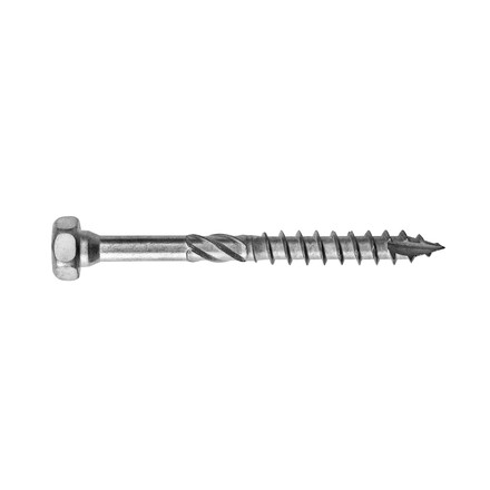
| SSH10.0 | 50 | 40 |
| SSH12.0 | 80 | 40 |
for lower distances, check ETA-06/0270 and EN1995
The minimum thickness of the supporting timber member to use with SSH10x40 is 38 mm.
Installation
Installation
Fasteners
On supported member:
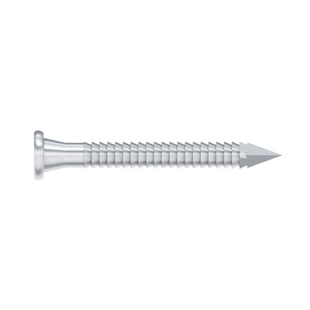
- CNA annular ring-shank nails dia. 4.0 x 50 mm.
- CNA annular ring-shank nails dia. 4.0 x 35 mm for thickness less than 64 mm.
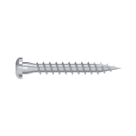
- CSA screws dia. 5.0 x 40 mm.
- CSA screws dia. 5.0 x 35 mm for thickness less than 60 mm.
On supporting member:
Wood substrate:
- CNA annular ring-shank nails dia. 4.0 x 50 mm.
- CNA annular ring-shank nails dia. 4.0 x 35 mm for thickness less than 64 mm.
- CSA screws dia. 5.0 x 40 mm.
- CSA screws dia. 5.0 x 35 mm for thickness less than 60 mm.
Steel substrate:
- Bolts dia. 10 mm (bolt diameter cannot be more than 2 mm smaller than the drill hole diameter).
Concrete substrate:
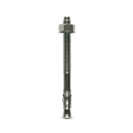
- Mechanical anchor dia. 10: WA M10-78/5 pin.
- Chemical anchor dia. 10: AT-HP resin + LMAS M10-120/25 threaded rod.
Hollow masonry substrate: (check the load bearing capacity of the anchors)
- Chemical anchor dia. 10: AT-HP or POLY-GP resin + LMAS M10-120/25 threaded rod + SH M16-130 screen.
Installation
Sur Bois :
- Tracer l’emplacement de la poutre portée sur le porteur,
- Présenter le sabot et préfixer les ailes de chaque côté,
- Ajuster le sabot par rapport aux tracés : le sabot doit être légèrement plus ouvert en haut que en bas pour faciliter l’installation de la poutre portée,
- Finaliser la fixation sur chaque aile,
- Présenter la poutre portée dans le sabot et la fixer en clouage partiel ou total.
Sur Béton :
- Méthode 1 : Tracer l’emplacement des perçages en appliquant le sabot sur la poutre,
- Méthode 2 : Tracer l’emplacement de la poutre sur le support, présenter le sabot et repérer les centres des perçages,
- Percer le support avec un forêt adapté,
- Présenter le sabot et fixer le sur le support avec des goujons d’ancrages,
- Présenter la poutre portée dans le sabot avant de la fixer.
