Angle brackets
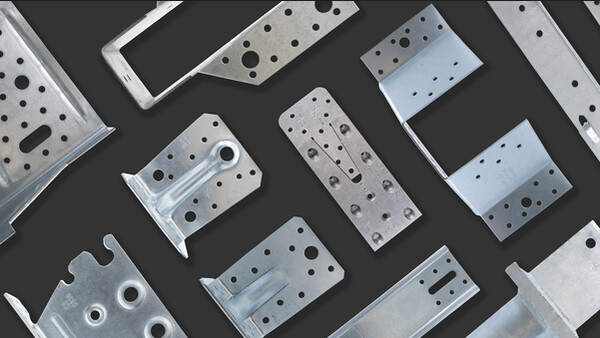
AB angle brackets are used for assemblies in supporting wood construction. The connectors are used in wood-wood assemblies, wood-concrete assemblies, exchanges etc.
Product Details
Features
Material
- Galvanized steel S250GD + Z275 according to NF EN 10346.
Benefits
Angle bracket for supporting constructions
Application
Suitable On
- Supporting member: solid wood, glued-laminated wood, concrete, steel, etc.
- Supported member: solid wood, composite lumber, glued-laminated wood, triangular trusses, profiles, etc.
When to Use
- Fastening of small trusses.
- Cladding plates, cladding uprights.
- Rafter anchors, cantilevers, headers, etc.
Technical Data
Simplified characteristic capacities - Timber beam to timber beam - Full nailing - Connection with 2 brackets
| References | Simplified product capacities - Beam to beam – Full nailing | |
|---|---|---|
| Number of Fasteners | ||
| Joist | Flange B | |
| Qty | Qty | |
| AB70 | - | - |
| AB90 | 6 | 9 |
| AB105 | 8 | 11 |
The load capacity belongs to a load group with the modification factor kmod.
1) R4/5,k is determined for beam width b = 75 mm and essentricity e = 130 mm. See ETA for other values of b and e.
If the overall structure prevents the rotation of the purlin, the load values R1,k and R2/3,k in an assembly with only one bracket equal to half of the given value in table 2. See ETA if the purlin is able to rotate.
* The published characteristic capacity is based on short term load duration and service class 2 according to EC5 (EN 1995) – kmod = 0.9. For other load duration and service class, please refer to the ETA to get more accurate capacities
To obtain the resistance values for a single bracket, the values in the above table should be divided by two, provided that the supported beam is locked in rotation. Please consult our ETA-06/0106 if the beam is free to rotate.
Simplified characteristic capacities - Timber beam to timber beam - Partial nailing - Connection with 2 brackets
| References | Simplified product capacities - Timber to timber – Partial nailing | |||||||||||
|---|---|---|---|---|---|---|---|---|---|---|---|---|
| Number of Fasteners | Simplified characteristic capacities - Timber C24 - 2 angle brackets per connection [kN] | |||||||||||
| Joist | Flange B | R1.k | R2.k = R3.k | |||||||||
| Qty | Type | Qty | Type | CNA4.0x35 | CNA4.0x40 | CNA4.0x50 | CNA4.0x60 | CNA4.0x35 | CNA4.0x40 | CNA4.0x50 | CNA4.0x60 | |
| AB70 | 2 | - | 3 | - | 3.2 | 3.9 | - | - | 3.4 | 3.8 | 5.2 | 5.6 |
| AB90 | 4 | - | 4 | - | 2.6 | 3.2 | 3.6 | 4.5 | 5 | 5.5 | 6.9 | 7.3 |
| AB105 | 4 | - | 5 | - | 4.3 | 5.3 | 6.1 | 7.6 | 3.6 | 4 | 7 | 7.5 |
To obtain the resistance values for a single bracket, the values in the above table should be divided by two, provided that the supported beam is locked in rotation. Please consult our ETA-06/0106 if the beam is free to rotate.
Simplified characteristic capacities - Timber beam to rigid support - Connection with 2 brackets
| References | Simplified product capacities - Timber beam to Concrete | |||
|---|---|---|---|---|
| Number of Fasteners | ||||
| Joist | Flange B | |||
| Qty | Type | Qty | Type | |
| AB90 | 5 | CNA* | 2 | Ø10 |
| AB105 | 5 | CNA* | 2 | Ø10 |
*The published characteristic capacity is based on short term load duration and service class 2 according to EC5 (EN 1995) – kmod = 0.9. For other load duration and service class, please refer to the ETA to get more accurate capacities.
Refer to Characteristic Capacity table columns for type of fasteners that can be used in Flange A. Capacities vary depending on fastener type used.
Refer to the Simpson Strong-Tie anchor product range for suitable anchors. Typical anchor solutions depend on the concrete type, spacing and edge distances.
To obtain the resistance values for a single bracket, the values in the above table should be divided by two, provided that the supported beam is locked in rotation. Please consult our ETA-06/0106 if the beam is free to rotate.
Wood/wood connection beam/beam type - assembly with 2 angle brackets
| References | Product capacities - Beam to beam - Full nailing | |||||||||||
|---|---|---|---|---|---|---|---|---|---|---|---|---|
| Number of Fasteners | Characteristic Capacities - Timber C24 - 2 angle brackets per connection [kN] | |||||||||||
| Joist | Flange B | R1.k (Tensile) | R2.k = R3.k (Shear) | R4.k = R5.k (1) | ||||||||
| Qty | Qty | CNA4.0x35 | CNA4.0x40 | CNA4.0x50 | CNA4.0x60 | CNA4.0x35 | CNA4.0x40 | CNA4.0x50 | CNA4.0x60 | CNA4.0x40 | CNA4.0x60 | |
| AB70 | 4 | 7 | 3.1/kmod^0.3 | 3.9/kmod^0.3 | 5.0/kmod^0.3 | - | 4.8 | 5.3 | 7 | 7.5 | 1.4/kmod^0.3 | - |
| AB90 | 6 | 9 | 4.2/kmod^0.3 | 5.1/kmod^0.3 | 6.7/kmod^0.3 | 7.5/kmod^0.3, max: 6.9/kmod | 6.8 | 7.1 | 9.4 | 10.4 | 1.9/kmod^0.3 | 2.5/kmod^0.5 |
| AB105 | 8 | 11 | 7.0/kmod^0.3 | 8.5/kmod^0.3 | 11.2/kmod^0.3 | 12.7/kmod^0.3 | 12.2 | 13.3 | 16.9 | 18.1 | 3.3/kmod^0.3 | 4.7/kmod^0.3 |
The load capacity belongs to a load group with the modification factor kmod.
1) R4/5,k is determined for beam width b = 75 mm and essentricity e = 130 mm. See ETA for other values of b and e.
If the overall structure prevents the rotation of the purlin, the load values R1,k and R2/3,k in an assembly with only one bracket equal to half of the given value in table 2. See ETA if the purlin is able to rotate.
Characteristic capacities - Timber beam to timber beam - Partial nailing - Connection with 2 brackets
| References | Capacities wood-wood connection / partialnailing | |||||||
|---|---|---|---|---|---|---|---|---|
| Number of Fasteners | Characteristic capacities - Timber C24 - 2 angle brackets per connection [kN] | |||||||
| Joist | Flange B | R1.k | R2.k = R3.k | R4.k = R5.k(1) | ||||
| Qty | Qty | CNA4.0x40 | CNA4.0x60 | CNA4.0x40 | CNA4.0x60 | CNA4.0x40 | CNA4.0x60 | |
| AB70 | 2 | 3 | 3.9/kmod^0.3 | - | 3.8 | 5.6 | 1.4/kmod^0.3 | - |
| AB90 | 4 | 4 | 3.1/kmod^0.3 | 4.4/kmod^0.3 | 5.5 | 7.3 | 1.2/kmod^0.5 | 1.7/kmod^0.3 |
| AB105 | 4 | 5 | 5.4/kmod^0.3 | 7.4/kmod^0.3 | 4 | 7.5 | 2.1/kmod^0.5 | 2.9/kmod^0.4 |
The load capacity belongs to a load group with the modification factor kmod.
1) R4/5,k is determined for beam width b = 75 mm and essentricity e = 130 mm. See ETA for other values of b and e.
If the overall structure prevents the rotation of the purlin, the load values R1,k and R2/3,k in an assembly with only one bracket equal to half of the given value in table 2. See ETA if the purlin is able to rotate.
Characteristic capacities - Timber beam to rigid support - Connection with 2 brackets
| References | Product capacities - Timber beam to concrete | |||||||||||
|---|---|---|---|---|---|---|---|---|---|---|---|---|
| Number of Fasteners | Characteristic capacities - Timber C24 - 2 angle brackets per connection [kN] | |||||||||||
| Joist | Flange B | R1.k | R2.k = R3.k | |||||||||
| Qty | Type | Qty | Type | CNA4.0x35 | CNA4.0x40 | CNA4.0x50 | CNA4.0x60 | CNA4.0x35 | CNA4.0x40 | CNA4.0x50 | CNA4.0x60 | |
| AB90 | 5 | CNA* | 2 | Ø10 | 5.4/kmod | 5.4/kmod | 5.4/kmod | 5.4/kmod | 4.73 | 5.03 | 6.3 | 6.66 |
| AB105 | 5 | CNA* | 2 | Ø10 | min (12.3 ; 11.3/kmod) | min (13.7 ; 11.3/kmod) | min (17.5 ; 11.3/kmod) | min (19.7 ; 11.3/kmod) | 4.8 | 5.1 | 6.4 | 6.8 |
Refer to Characteristic Capacity table columns for type of fasteners that can be used in Flange A. Capacities vary depending on fastener type used.
Refer to the Simpson Strong-Tie anchor product range for suitable anchors. Typical anchor solutions depend on the concrete type, spacing and edge distances.
To obtain the resistance values for a single bracket, the values in the above table should be divided by two, provided that the supported beam is locked in rotation. Please consult our ETA-06/0106 if the beam is free to rotate.
Characteristic capacities - Timber beam to timber column - Connection with 1 bracket
| References | Product capacities - Timber beam to column | |||||||
|---|---|---|---|---|---|---|---|---|
| Number of Fasteners | Characteristic Capacities [kN] | |||||||
| Joist | Flange B | R1.k | R2.k | |||||
| Qty | Qty | Flap turned downwards | Flap turned upwards | CNA4.0x40 | CNA4.0x60 | |||
| CNA4.0x40 | CNA4.0x60 | CNA4.0x40 | CNA4.0x60 | |||||
| AB90 | 4 | 4 | 5.2/ kmod^0.55 | 5.2/ kmod^0.55 | 4.0/ kmod^0.5 | 4.0/ kmod^0.5 | 0.7/ kmod | 0.7/ kmod |
| AB105 | 6 | 5 | 10,0; max:9,8/ kmod | 9.4/ kmod^0.6 | 8.1/ kmod^0.75 | 8.1/ kmod^0.75 | 1.4/ kmod | 1.4/ kmod |
The load capacity belongs to a load group with the modification factor kmod
Installation
Installation
Fixing
Wood:
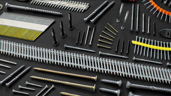
- CNA annular ring-shank nails dia. 4.0 x 35 or dia. 4.0 x 50 mm.
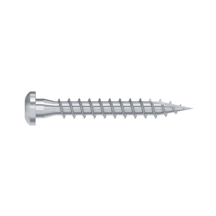
- CSA screws dia. 5.0 x 35 mm or CSA screws dia. 5.0 x 40 mm.
- Bolts.
- LAG screws.
Concrete:
Concrete substrate
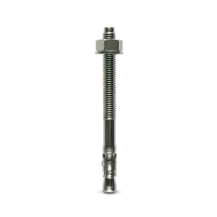
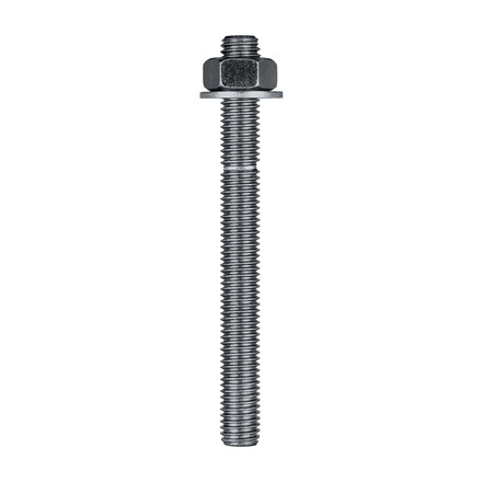
- Mechanical anchor: WA M10-78/5 OR WA M12-104/5 pin.
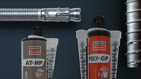
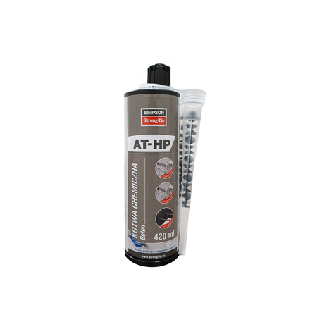
- Chemical anchor: AT-HP resin + LMAS M10-120/25 or LMAS M12-150/35 threaded rod.
Hollow masonry substrate:
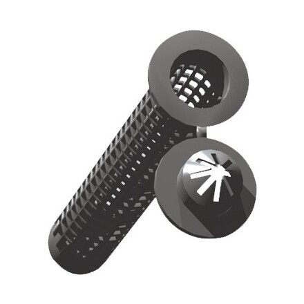
- Chemical anchor: AT-HP or POLY-GP resin + LMAS M12-150/35 threaded rod + SH M16-130 screen.
On steel:
- Bolts.
Technical information
F1: tensile force in the central axis of the angle-bracket
Particular situation of a fastening with only one angle-bracket:
- If the overall structure prevents the rotation of the purlin or the post, the tensile strength is equal to half of the given value for two angle-brackets.
- Otherwise, the connection resistance depends on the « f » distance between the vertical contact surface and the point of load application.
F2 and F3: shear lateral force
Particular situation of a connection with only one angle-bracket:
- The resistance value to consider is equal to half of the one given for two angle-brackets.
F4 and F5: transversal force directed towards or opposite the angle-bracket
- The connection resistance depends on the « e » distance between the base of the angle-bracket and the point of load application.
- To consult corresponding loads, contact us.
Only F1, F2 and F3 forces for connections with 2 angle-brackets are present on this sheet.
For more information, contact us.
