High Performance Resin
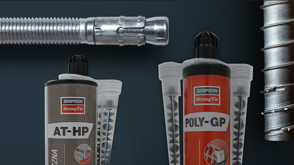
AT-HP is a styrene free methacrylate resin suitable for high performance fixing applications in threaded rod into concrete.
- Easy to dispense and fast curing, it's specially designed for structural fixings and construction uses.
- ETA Option 8 for threaded rod and rebar
Product Details
Features
Material
- Styrene free methacrylate resin.
- Threaded rod: galvanised steel and stainless steel A4-70.
Benefits
- Fast curing.
- Low odour.
- Non-flammable.
- Easy to dispense.
Application
Header member
- Non-cracked concrete.
- Solid blocks.
- Hollow blocks.
- AAC Blocks.
For Use With
- Threaded rod and rebar connections.
- Racking.
- Balconies.
- Facades.
Technical Data
Références
| References | Product information | ||||
|---|---|---|---|---|---|
| Grey color | Beige color | Content [ml] | Weight [kg] | Packaging qty [pcs] | |
| ATHP300BG-PL | x | - | 300 | 0.575 | 12 |
Design resistance – Tension – NRd [kN] – hef = 8d – Carbon steel 5.8
| References | Design resistance – hef = 8d – Carbon steel 5.8 | |||||||
|---|---|---|---|---|---|---|---|---|
| Tension - NRd [kN] | ||||||||
| Cracked concrete | Non-cracked concrete | |||||||
| C20/25 | C30/37 | C40/50 | C50/60 | C20/25 | C30/37 | C40/50 | C50/60 | |
| AT-HP + LMAS M10 | - | - | - | - | 15.9 | 17.8 | 19.3 | 19.3 |
Concrete :
1. The design loads have been calculated using the partial safety factors for resistances stated in ETA-approval(s). The loading figures are valid for unreinforced concrete and reinforced concrete with a rebar spacing s ≥ 15 cm (any diameter) or with a rebar spacing s ≥ 10 cm, if the rebar diameter is 10mm or smaller.
2. The figures for shear are based on a single anchor without influence of concrete edges. For anchorages close to edges (c ≤ max [10 hef; 60d]) the concrete edge failure shall be checked per ETAG 001, Annex C, design method A.
3. Concrete is considered non-cracked when the tensile stress within the concrete is\sigmaL +\sigmaR ≤ 0. In the absence of detailed verification\sigmaR = 3 N/mm² can be assumed (\sigmaL equals the tensile stress within the concrete induced by external loads, anchors loads included).
Design resistance – Tension – NRd [kN] – hef = 12d – Carbon steel 5.8
| References | Design resistance – hef = 12d – Carbon steel 5.8 | |||||||
|---|---|---|---|---|---|---|---|---|
| Tension - NRd [kN] | ||||||||
| Cracked concrete | Non-cracked concrete | |||||||
| C20/25 | C30/37 | C40/50 | C50/60 | C20/25 | C30/37 | C40/50 | C50/60 | |
| AT-HP + LMAS M10 | - | - | - | - | 19.3 | 19.3 | 19.3 | 19.3 |
Concrete :
1. The design loads have been calculated using the partial safety factors for resistances stated in ETA-approval(s). The loading figures are valid for unreinforced concrete and reinforced concrete with a rebar spacing s ≥ 15 cm (any diameter) or with a rebar spacing s ≥ 10 cm, if the rebar diameter is 10mm or smaller.
2. The figures for shear are based on a single anchor without influence of concrete edges. For anchorages close to edges (c ≤ max [10 hef; 60d]) the concrete edge failure shall be checked per ETAG 001, Annex C, design method A.
3. Concrete is considered non-cracked when the tensile stress within the concrete is\sigmaL +\sigmaR ≤ 0. In the absence of detailed verification\sigmaR = 3 N/mm² can be assumed (\sigmaL equals the tensile stress within the concrete induced by external loads, anchors loads included).
Design resistance – Tension – NRd [kN] – hef = 8d – Stainless steel A4-70
| References | Design resistance – hef = 8d – Stainless steel A4-70 | |||||||
|---|---|---|---|---|---|---|---|---|
| Tension - NRd [kN] | ||||||||
| Cracked concrete | Non-cracked concrete | |||||||
| C20/25 | C30/37 | C40/50 | C50/60 | C20/25 | C30/37 | C40/50 | C50/60 | |
| ATHP300BG-PL | - | - | - | - | - | - | - | - |
| AT-HP + LMAS M10 | - | - | - | - | 15.9 | 17.8 | 19.6 | 20.7 |
Concrete :
1. The design loads have been calculated using the partial safety factors for resistances stated in ETA-approval(s). The loading figures are valid for unreinforced concrete and reinforced concrete with a rebar spacing s ≥ 15 cm (any diameter) or with a rebar spacing s ≥ 10 cm, if the rebar diameter is 10mm or smaller.
2. The figures for shear are based on a single anchor without influence of concrete edges. For anchorages close to edges (c ≤ max [10 hef; 60d]) the concrete edge failure shall be checked per ETAG 001, Annex C, design method A.
3. Concrete is considered non-cracked when the tensile stress within the concrete is\sigmaL +\sigmaR ≤ 0. In the absence of detailed verification\sigmaR = 3 N/mm² can be assumed (\sigmaL equals the tensile stress within the concrete induced by external loads, anchors loads included).
Design resistance – Tension – NRd [kN] – hef = 12d – Stainless steel A4-70
| References | Design resistance – hef = 12d – Stainless steel A4-70 | |||||||
|---|---|---|---|---|---|---|---|---|
| Tension - NRd [kN] | ||||||||
| Cracked concrete | Non-cracked concrete | |||||||
| C20/25 | C30/37 | C40/50 | C50/60 | C20/25 | C30/37 | C40/50 | C50/60 | |
| AT-HP + LMAS M10 | - | - | - | - | 21.9 | 21.9 | 21.9 | 21.9 |
Concrete :
1. The design loads have been calculated using the partial safety factors for resistances stated in ETA-approval(s). The loading figures are valid for unreinforced concrete and reinforced concrete with a rebar spacing s ≥ 15 cm (any diameter) or with a rebar spacing s ≥ 10 cm, if the rebar diameter is 10mm or smaller.
2. The figures for shear are based on a single anchor without influence of concrete edges. For anchorages close to edges (c ≤ max [10 hef; 60d]) the concrete edge failure shall be checked per ETAG 001, Annex C, design method A.
3. Concrete is considered non-cracked when the tensile stress within the concrete is\sigmaL +\sigmaR ≤ 0. In the absence of detailed verification\sigmaR = 3 N/mm² can be assumed (\sigmaL equals the tensile stress within the concrete induced by external loads, anchors loads included).
Design resistance – Shear – VRd [kN] – hef = 8d – Carbon steel 5.8
| References | Design resistance – hef = 8d – Carbon steel 5.8 | |||||||
|---|---|---|---|---|---|---|---|---|
| Shear - VRd [kN] | ||||||||
| Cracked concrete | Non-cracked concrete | |||||||
| C20/25 | C30/37 | C40/50 | C50/60 | C20/25 | C30/37 | C40/50 | C50/60 | |
| AT-HP + LMAS M10 | - | - | - | - | 12 | 12 | 12 | 12 |
Concrete :
1. The design loads have been calculated using the partial safety factors for resistances stated in ETA-approval(s). The loading figures are valid for unreinforced concrete and reinforced concrete with a rebar spacing s ≥ 15 cm (any diameter) or with a rebar spacing s ≥ 10 cm, if the rebar diameter is 10mm or smaller.
2. The figures for shear are based on a single anchor without influence of concrete edges. For anchorages close to edges (c ≤ max [10 hef; 60d]) the concrete edge failure shall be checked per ETAG 001, Annex C, design method A.
3. Concrete is considered non-cracked when the tensile stress within the concrete is\sigmaL +\sigmaR ≤ 0. In the absence of detailed verification\sigmaR = 3 N/mm² can be assumed (\sigmaL equals the tensile stress within the concrete induced by external loads, anchors loads included).
Design resistance – Shear – VRd [kN] – hef = 12d – Carbon steel 5.8
| References | Design resistance – hef = 12d – Carbon steel 5.8 | |||||||
|---|---|---|---|---|---|---|---|---|
| Shear - VRd [kN] | ||||||||
| Cracked concrete | Non-cracked concrete | |||||||
| C20/25 | C30/37 | C40/50 | C50/60 | C20/25 | C30/37 | C40/50 | C50/60 | |
| AT-HP + LMAS M10 | - | - | - | - | 12 | 12 | 12 | 12 |
Concrete :
1. The design loads have been calculated using the partial safety factors for resistances stated in ETA-approval(s). The loading figures are valid for unreinforced concrete and reinforced concrete with a rebar spacing s ≥ 15 cm (any diameter) or with a rebar spacing s ≥ 10 cm, if the rebar diameter is 10mm or smaller.
2. The figures for shear are based on a single anchor without influence of concrete edges. For anchorages close to edges (c ≤ max [10 hef; 60d]) the concrete edge failure shall be checked per ETAG 001, Annex C, design method A.
3. Concrete is considered non-cracked when the tensile stress within the concrete is\sigmaL +\sigmaR ≤ 0. In the absence of detailed verification\sigmaR = 3 N/mm² can be assumed (\sigmaL equals the tensile stress within the concrete induced by external loads, anchors loads included).
Design resistance – Shear – VRd [kN] – hef = 8d – Stainless steel A4-70
| References | Design resistance – hef = 8d – Stainless steel A4-70 | |||||||
|---|---|---|---|---|---|---|---|---|
| Shear - VRd [kN] | ||||||||
| Cracked concrete | Non-cracked concrete | |||||||
| C20/25 | C30/37 | C40/50 | C50/60 | C20/25 | C30/37 | C40/50 | C50/60 | |
| AT-HP + LMAS M10 | - | - | - | - | 12.8 | 12.8 | 12.8 | 12.8 |
Concrete :
1. The design loads have been calculated using the partial safety factors for resistances stated in ETA-approval(s). The loading figures are valid for unreinforced concrete and reinforced concrete with a rebar spacing s ≥ 15 cm (any diameter) or with a rebar spacing s ≥ 10 cm, if the rebar diameter is 10mm or smaller.
2. The figures for shear are based on a single anchor without influence of concrete edges. For anchorages close to edges (c ≤ max [10 hef; 60d]) the concrete edge failure shall be checked per ETAG 001, Annex C, design method A.
3. Concrete is considered non-cracked when the tensile stress within the concrete is\sigmaL +\sigmaR ≤ 0. In the absence of detailed verification\sigmaR = 3 N/mm² can be assumed (\sigmaL equals the tensile stress within the concrete induced by external loads, anchors loads included).
Design resistance – Shear - VRd [kN] – hef = 12d – Stainless steel A4-70
| References | Design resistance – hef = 12d – Stainless steel A4-70 | |||||||
|---|---|---|---|---|---|---|---|---|
| Shear - VRd [kN] | ||||||||
| Cracked concrete | Non-cracked concrete | |||||||
| C20/25 | C30/37 | C40/50 | C50/60 | C20/25 | C30/37 | C40/50 | C50/60 | |
| AT-HP + LMAS M10 | - | - | - | - | 12.8 | 12.8 | 12.8 | 12.8 |
Concrete :
1. The design loads have been calculated using the partial safety factors for resistances stated in ETA-approval(s). The loading figures are valid for unreinforced concrete and reinforced concrete with a rebar spacing s ≥ 15 cm (any diameter) or with a rebar spacing s ≥ 10 cm, if the rebar diameter is 10mm or smaller.
2. The figures for shear are based on a single anchor without influence of concrete edges. For anchorages close to edges (c ≤ max [10 hef; 60d]) the concrete edge failure shall be checked per ETAG 001, Annex C, design method A.
3. Concrete is considered non-cracked when the tensile stress within the concrete is\sigmaL +\sigmaR ≤ 0. In the absence of detailed verification\sigmaR = 3 N/mm² can be assumed (\sigmaL equals the tensile stress within the concrete induced by external loads, anchors loads included).
Design resistance – Bending moment – MRd [Nm] – Concrete
| References | Design resistance – Bending moment – MRd [Nm] | |
|---|---|---|
| Carbon steel 5.8 | Stainless steel A4-70 | |
| AT-HP + LMAS M10 | 29.6 | 34 |
Concrete :
1. The design loads have been calculated using the partial safety factors for resistances stated in ETA-approval(s). The loading figures are valid for unreinforced concrete and reinforced concrete with a rebar spacing s ≥ 15 cm (any diameter) or with a rebar spacing s ≥ 10 cm, if the rebar diameter is 10mm or smaller.
2. The figures for shear are based on a single anchor without influence of concrete edges. For anchorages close to edges (c ≤ max [10 hef; 60d]) the concrete edge failure shall be checked per ETAG 001, Annex C, design method A.
3. Concrete is considered non-cracked when the tensile stress within the concrete is\sigmaL +\sigmaR ≤ 0. In the absence of detailed verification\sigmaR = 3 N/mm² can be assumed (\sigmaL equals the tensile stress within the concrete induced by external loads, anchors loads included).
Design resistance – Tension – NRd [kN] – Rebar
| References | Design resistance – NRd – Carbon steel 5.8 [kN] | |||||||
|---|---|---|---|---|---|---|---|---|
| Non-cracked concrete | ||||||||
| hef = 8d | hef = 12d | |||||||
| C20/25 | C30/37 | C40/50 | C50/60 | C20/25 | C30/37 | C40/50 | C50/60 | |
| AT-HP + Ø8 | 6.3 | 7 | 7.7 | 8.1 | 9.4 | 10.5 | 11.5 | 12.2 |
| AT-HP + Ø12 | 14.1 | 15.8 | 17.3 | 18.3 | 21.1 | 23.6 | 26 | 27.4 |
| AT-HP + Ø14 | 19.1 | 21.4 | 23.6 | 24.9 | 28.7 | 32.2 | 35.3 | 37.3 |
| AT-HP + Ø16 | 23.2 | 26 | 28.6 | 34.8 | 34.8 | 39 | 42.8 | 52.2 |
| AT-HP + Ø20 | 36.3 | 40.6 | 44.6 | 47.2 | 54.4 | 61 | 66.9 | 70.8 |
| AT-HP + Ø25 | 52.3 | 58.6 | 64.4 | 68 | 78.5 | 87.9 | 96.6 | 102.1 |
Design resistance – Shear – VRd [kN] – Rebar
| References | Design resistance – VRd – Carbon steel 5.8 [kN] | |||||||
|---|---|---|---|---|---|---|---|---|
| Non-cracked concrete | ||||||||
| hef = 8d | hef = 12d | |||||||
| C20/25 | C30/37 | C40/50 | C50/60 | C20/25 | C30/37 | C40/50 | C50/60 | |
| AT-HP + Ø8 | 9.3 | 9.3 | 9.3 | 9.3 | 9.3 | 9.3 | 9.3 | 9.3 |
| AT-HP + Ø12 | 20.7 | 20.7 | 20.7 | 20.7 | 20.7 | 20.7 | 20.7 | 20.7 |
| AT-HP + Ø14 | 28 | 28 | 28 | 28 | 28 | 28 | 28 | 28 |
| AT-HP + Ø16 | 36.7 | 36.7 | 36.7 | 36.7 | 36.7 | 36.7 | 36.7 | 36.7 |
| AT-HP + Ø20 | 57.3 | 57.3 | 57.3 | 57.3 | 57.3 | 57.3 | 57.3 | 57.3 |
| AT-HP + Ø25 | 90 | 90 | 90 | 90 | 90 | 90 | 90 | 90 |
Design resistance – Bending moment – MRd [Nm] – Rebar
| References | Design resistance – Bending moment – MRd [Nm] |
|---|---|
| AT-HP + Ø8 | 22 |
| AT-HP + Ø12 | 74.7 |
| AT-HP + Ø14 | 118.7 |
| AT-HP + Ø16 | 176.7 |
| AT-HP + Ø20 | 345.3 |
| AT-HP + Ø25 | 674.7 |
Installation
Installation
Curing Schedule
Temperature of the anchorage base Tbase material | Working time (Gel time) tgel | Curing time (in dry concrete) tcure, dry | Curing time (in wet concrete) tcure, wet |
|---|---|---|---|
| 0°C ≤ Tbase material < +5°C | 25 min | 90 min | 3:00 h |
| 5°C ≤ Tbase material < +10°C | 17 min | 70 min | 2:20 h |
| 10°C ≤ Tbase material < +20°C | 12 min | 65 min | 2:10 h |
| 20°C ≤ Tbase material < +30°C | 6 min | 60 min | 2:00 h |
| 30°C ≤ Tbase material ≤ +40°C | 3 min | 45 min | 1:30 h |
• Manual Air Cleaning (MAC) for all drill hole diameters d0 ≤ 24 mm and drill holl depth h0 ≤ 10d :
4x blowing (hand pump)
4x brushing
4x blowing (Hand pump)
• Compressed Air Cleaning (CAC) for all drill hole diameters d0 and drill hole depths :
2x blowing (min. 6 bar - oil free compressed air)
2x brushing
2x blowing (min. 6 bar - oil free compressed air)
• Cartridge temperature (Bond material) : ≥ +20°C
Drilling methods
| Solid brick/concrete | Percussion/hammer drilling |
| Hollow/perforated brick | Rotation drilling |
| Aerated concrete | Percussion/hammer drilling |
Installation parameters – Concrete
| References | Installation parameters - Concrete | |||||
|---|---|---|---|---|---|---|
| Ø drilling [d0] [mm] | Max. fixture hole Ø [df] [mm] | Drilling depth (8d) [h0=hef=8d] [mm] | Drilling depth (12d) [h0=hef=12d] [mm] | Wrench size [SW] | Installation torque [Tinst] [Nm] | |
| AT-HP + LMAS M10 | 12 | 12 | 80 | 120 | 17 | 20 |
Spacing, edge distances and member thickness - Concrete
| References | Spacing, edge distance and member thickness - Concrete | |||||||||
|---|---|---|---|---|---|---|---|---|---|---|
| Effective embedment depth (8d) [hef,8d] [mm] | Characteristic spacing for hef,8d [Scr,N] [mm] | Characteristic edge distance for hef,8d [ccr,N] [mm] | Min. member thickness for hef,8d [hmin] [mm] | Effective embedment depth (12d) [hef,12d] [mm] | Characteristic spacing for hef,12d [Scr,N] [mm] | Characteristic edge distance for hef,12d [ccr,N] [mm] | Min. member thickness for hef,12d [hmin] [mm] | Min. spacing [Smin] [mm] | Min. edge distance [Cmin] [mm] | |
| AT-HP + LMAS M10 | 80 | 240 | 120 | 110 | 120 | 360 | 180 | 150 | 50 | 50 |
Installation parameters – Rebar
| References | Installation parameters - Rebar | ||
|---|---|---|---|
| Ø drilling [d0] [mm] | Drilling depth (8d) [h0=hef=8d] [mm] | Drilling depth (12d) [h0=hef=12d] [mm] | |
| AT-HP + Ø8 | 12 | 64 | 96 |
| AT-HP + Ø12 | 16 | 96 | 144 |
| AT-HP + Ø14 | 18 | 112 | 168 |
| AT-HP + Ø16 | 20 | 128 | 192 |
| AT-HP + Ø20 | 25 | 160 | 240 |
| AT-HP + Ø25 | 32 | 200 | 300 |
Spacing, edge distances and member thickness – Rebar
| References | Spacing, edge distance and member thickness - Rebar | |||||||||
|---|---|---|---|---|---|---|---|---|---|---|
| Effective embedment depth (8d) [hef,8d] [mm] | Characteristic spacing for hef,8d [Scr,N] [mm] | Characteristic edge distance for hef,8d [ccr,N] [mm] | Min. member thickness for hef,8d [hmin] [mm] | Effective embedment depth (12d) [hef,12d] [mm] | Characteristic spacing for hef,12d [Scr,N] [mm] | Characteristic edge distance for hef,12d [ccr,N] [mm] | Min. member thickness for hef,12d [hmin] [mm] | Min. spacing [Smin] [mm] | Min. edge distance [Cmin] [mm] | |
| AT-HP + Ø8 | 64 | 192 | 96 | 100 | 96 | 288 | 144 | 100 | 40 | 40 |
| AT-HP + Ø12 | 96 | 288 | 144 | 126 | 144 | 432 | 216 | 174 | 60 | 60 |
| AT-HP + Ø14 | 112 | 336 | 168 | 148 | 168 | 504 | 252 | 204 | 70 | 70 |
| AT-HP + Ø16 | 128 | 384 | 192 | 168 | 192 | 576 | 288 | 232 | 80 | 80 |
| AT-HP + Ø20 | 160 | 480 | 240 | 210 | 240 | 720 | 360 | 290 | 100 | 100 |
| AT-HP + Ø25 | 200 | 600 | 300 | 264 | 300 | 900 | 450 | 364 | 125 | 125 |
